|
Engines for F3D Pylon Racing Models |
| During the 1970s various engines were used for
pylon racing models, e.g. the Hirtenberger HP 40
or the Webra .40 Pylon or the
K&B .40. Since it's debut in 1974, the Italian
OPS .40 Pylon had become the dominant engine in
Europe. The SuperTigre X-40, which became
available in the same year, has never been so popular in Europe, but has
been widely used in the USA. There, he was a main competitor of the K&B
racing engines. In the 1980s, the OPS got a quite powerful rival: the
Italian PICCO .40 Pylon engine. Later, the
Malina brothers from Czechoslovakia became very successful with their
ABC version of the
MVVS .40 GRRT. The Italian Rossi brothers had
been producing powerful .15 and .60 engines for some years, but pylon
enthusiasts had to wait rather long for the competitive
Rossi R40 Pylon to finally appear. |
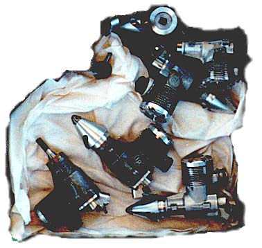 A bunch of IR engines in the box of Manfred Pick. |
| In 1990 the first samples of the North American
Nelson .40 Pylon engine appeared and proved
to be very powerful - even out of the box, without the tuning work, which
the OPS usually required. In more recent years, pilots from the Netherlands
started to use proprietary engines from the control line specialists
Metkemeijer. These engines are
manufactured in small numbers only and thus cannot be cheap. Today, there are several good engines for pylon racing available, ranging from these "stock" engines to specially crafted engines from countries of the former Soviet Union («IR» from R. Ibragimov, «Cyclon» from Alexander Kalmykov or the « Since about 1998, front intake engines are seen more and more often, after 20 years of rear intakes dominating the scene. I am not sure, whether this is a new fashion or whether the improved cooling and mixing behavior of such engines is the reason for this. Part of the story might also be the critical gap adjustment of the rear inlet disk valves and their friction losses. |
 Finally you understand, what a «split second» stands for! |
Of course, the manufacturing numbers for pylon racing engines are tiny, compared with engines for the average modeler or powerboats and cars. On the other hand, some pilots do not hesitate to fork out some extra bucks for a perfectly manufactured and powerful engine, which makes the business interesting for smaller companies and specialists. Nevertheless, we can safely assume, that no manufacturer of pylon racing engines will get rich - at least not from manufacturing and selling these engines.
| The possible tuning work to maximize the power
output concentrates on the following areas:
Some parameters are dependent on atmospheric conditions and have to be changed accordingly. This is the reason, why you can see people flipping through small booklets with lots of numbers during a racing event: they are looking up values for compression ratio, tuned pipe length, glow plug selection for their specific engine and propeller, which had proven to be optimal under similar conditions. Some of them even have replaced their booklets by a small computer, which interpolates between the values. Left: A tuned pipe, as it is used on a .40 pylon racing engine. |
| The serious pylon racer needs to know about the
power output of his engine. It does not matter whether he mechanically
modifies the engine, or just performs the final tuning by adjusting the
compression ratio and the length of the tuned pipe, or by selecting the best
glow plug. In general it is not necessary to know the power output of the
engine exactly in Watt or h.p.; instead, it is sufficient to compare the
rotational speed with a known propeller.
Comparing the r.p.m. values for different engine adjustments should lead to the maximum power output. It might be interesting, that the power to turn a propeller depends on the rotational speed to the power of 3. |
 Oops... |
 Not again! |
This means, that an increase in speed from
20000 1/min to 20500 1/min corresponds to a power increase of
(20500/20000)³ - 1.0 = 0.077 which means 7.7 % more power.
Achieving the same difference of 500 1/min at a base speed of
25000 1/min results in a power increase of (25500/25000)³ - 1.0 =
0.061 which corresponds to 6.1 % of the initial power.
We also know, that the power required to pull the model through the air depends on the speed of the model to the power of 3. The relation between power and speed for two cases 1 and 2 can be written as
Thus the above power increase of 6.1 % could lead to a speed increase of
To make things more complex, the engine speeds up, when the model is in the air, depending on the propeller characteristics. Also, the fuel supply system is of influence on engine behavior and power. Usually a closed fuel tank is used, which is pressurized by exhaust pressure or crankcase pressure from the engine. Both systems have their advantages and disadvantages, but for beginners it is more advisable to use exhaust pressure. There are also tanks available, which separate air and fuel by a rubber membrane, which helps to suppress the development of foam and bubbles in the fuel line. |
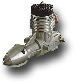
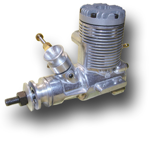
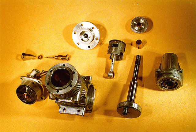
| OPS .40 Pylon | |
 |
The final variant of this engine with a special, pressed in steel front housing was called the .40 MI-SSP. OPS 40 Pylon stroke: 17.8 mm (engine has been donated by Ralph Freckmann, Germany) |
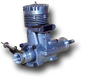
| Rossi R40 Pylon | |
|
|
The italian Rossi R40 Pylon engine. Modified versions of this engine by Ranjit Phelan / Australia were competitive in 2001/2002. |
| PICCO P 40 Pylon | |
|
 |
| PICCO P 40 Pylon
stroke: 20.2 mm Manufactured by PICCO Micromotori, Monza, Italy |
|
| Webra Speed 40 Pylon | |
 |
Webra built this modification of its
widely used Speed 40 which was available with an «L» piston ring or with an
ABC piston/liner. The modifications included extended timing, a venturi
carburetor and a pressure tap at the rear of the cylinder. While it was an
interesting and, due to its mono-bloc casing, lightweight engine, the Speed
40 Pylon never played an important role in pylon racing, but was a nice
sport and training engine. Power was quoted
as 1.0 kW at 16000 rpm. Webra Speed 40 Pylon stroke: 19 mm |
| HP 40 R | |
 [click on image for larger view] |
The HP 40 R-PR, designed by Peter Billes and built since 1972 by Hirtenberger in Austria, was one of the first engines developed especially for pylon racing. Its sophisticated Schnuerle porting system was responsible for the remarkable power output of 0.89 kW at 21000 rpm. Thus it was able to surpass the K&B Torpedo models 70 and 71. The rear rotary disk intake system avoided lengthy gas passages and reduced the crankcase volume. But it still featured a ringed piston, which prohibited the use of wide port openings in the cylinder sleeve. |
| This cut drawing of the HP 40 R-PR
demonstrates, that the engine already showed important details of a modern
pylon racing engine: rear intake, a lightweight piston and wide, a closed
crank web, well rounded gas channels.
HP .40 R-PR stroke: 18.6 mm |
 |
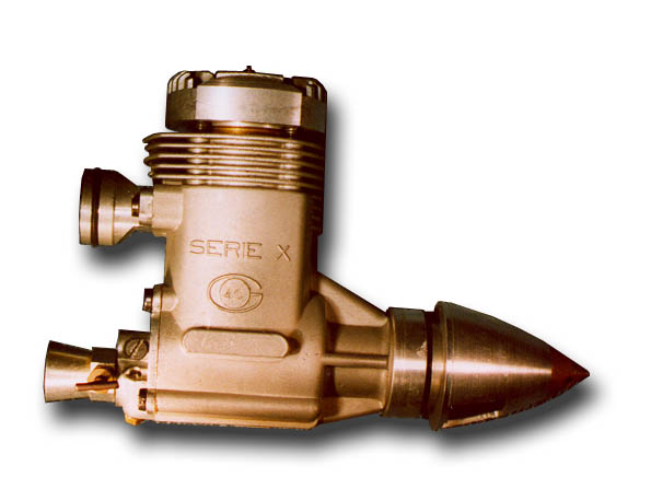
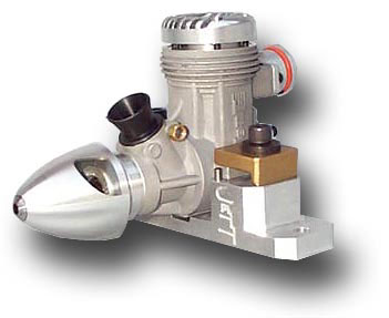
| Super Tiger ST X .40 Glow | |
|
Super Tigre engines from Italy are well known for their high performance. The world speed record for R/C models by W. Käseberg in 1968 was set up with a G 60 RV ABC engine, and the X .15 engines were used in different FAI classes. The X .40 was developed together with the X .29 speed engine and has also been widely used in the USA, often tuned by engine experts, like Terry Prather in the 1970s. Italian manufacturers like Super Tiger, Rossi and OPS pioneered the ABC piston sleeve system (aluminum piston, chromed brass cylinder) which will yield lower friction than a ringed piston when fitted properly. Super Tigre ST X .40 stroke: 21.5 mm |
|
| MVVS 6,5 GRRT | ||
An older MVVS 6,5 GRRT built in former Czechoslovakia around 1983. The upper part of the cylinder can be rotated in steps of 90°. |
Since the 1950s, MVVS engines could be
seen in the first places of national and international championships. The
driving forces behind the .40 pylon racing engines were the Malina brothers. The initial GRRT (left) has a steel sleeve and a ringed piston. The Malina brothers used their own ABC piston/sleeve combination to win the 1985 FAI F3D world championships. There is a special version of the GRRT pylon engine with 6-point suspension available (shown below). As I have been told, Nelson parts can be used for conrod, bearings and rotary valve.
|
|
 A standard MVVS .40 GRRT Pylon Racing Engine (1988). |
MVVS 6,5 GRRT stroke: 19.0 mm |
|
| Nelson 40 FAI | |
| The Nelson 40 FAI Pylon Racing engine was first
used at the 1990 AMA Nationals, where it performed well enough to capture
four of the five top spots. It is available in different flavors to suit the
Formula I as well as the FAI racer. Whereas the
Formula I version is optimized for high nitro fuel and a mini pipe, the
FAI version, as it is used in Europe, is set up for a tuned pipe
and no nitro.
There are also versions available for the Quickie 500 (Q500) racing events in the United States (the German beginners class also use the Quickie 500, but the engine is unlimited). The fathers of the engine are the pylon experts Dave Shadel and Jim Shinohara and engine designer Henry Nelson, the mother is unknown. |
Source: |
| OS-MAX .40 SR | |||
|
|
||
| OS-MAX .40 PS | |||
|
|
||
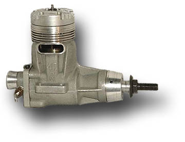
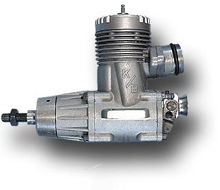
| K&B .40 Racing Engines | |
 |
This is one of the early K&B engines, a lightweight «Torpedo», which has been modified by engine expert Clarence Lee to increase its power output. It was used mainly in pylon racing models. The piston was already equipped with an L-ring, but the engine was still using the traditional cross flow scavenging system. K&B .40 Torpedo - Lee Custom stroke: 19 mm (engine has been donated by Ralph Freckmann, Germany) |
|
|
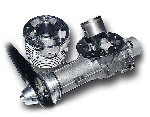
The next step in performance was achieved by changing the scavenging to
the Schnürle System. The piston was still equipped with an L-ring, the
standard for high performance model engines before the widespread use of the
ABC piston-sleeve combination.
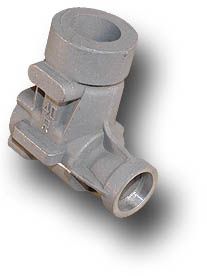
The K&B .40 R engine was made in a small production run to meet the racing rules requiring a minimum run of 100 engines (according to K&B advertising). This engine however is #112 which indicates that more engines were made. Engine specialist Clarence Lee knows, that 102 engines were produced in the first batch, of which only very few were held back due to low performance. A few additional engines were produced later - the highest serial number known to him is #114. This particular engine is owned by John Hall and has had the exhaust stack cut down to fit in a cowl and a simple sprinkler type carburetor installed. Most of these engines were passed out to elite racers and during the 1972 season they won the titles of NMPRA Champion and AMA Nats Campion in Formula I pylon racing. K&B .40 R stroke: 19 mm Sources: So far I was able to find a very rare raw casting of the crankcase, but I am still looking for a complete engine. Would consider swapping the casting for an engine) |
 |
This is a K&B .40 S with Schnuerle porting, which was successful in
Lakehurst (1974). It resembles its predecessor, the .40 R shown above but
was produced in larger quantities. The piston is still equipped with an
L-ring.
K&B .40 S SN #001471 |
|
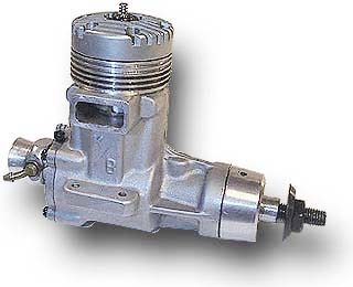
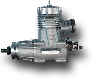
Two samples of Bill Wisniewski's pylon racing engine design are shown on
the left.
At first, both engines look similar, but a closer look shows that they have different crankcases, backplates, cylinders, cylinder heads, etc. Both have ABC piston/sleeve combinations and were flown with a short exhaust pipe only - not a tuned pipe. Today this would be impossible on the one hand due to the ear splitting noise and on the other hand because of the additional power which can be gained with a full length tuned pipe. The upper engine is serial #(1?) 0497, the lower bears no number. We also remember that Bill has been the first to use a tuned pipe with his TWA .15 engines in control line speed. K&B .40 SR II stroke: 19 mm |
| Cyclon-40 Eagle | ||
|
mass: 375 g |
A Cyclon-40 Eagle, one of
a series of pylon racing engines manufactured in Russia. The Cyclon-40 Turbo
(how I love those names) front intake / rear exhaust is rated at 3.2 kW at
31000 rpm; it weighs 310 grams. Like most modern pylon racing engines, it
features additional mounting lugs between the bearings to reduce crankcase
warping and bending. The cylinder head is a screw-on cap and fits Nelson
glow plugs. The engine is beautifully manufactured by Alexander Kalmykov in
Novosibirsk, who is also manufacturing several smaller competition engines
for free flight and control line models. For my test results and some photos of this engine jump to «Performance of a Cyclon Pylon Racing Engine». |
|
|
Source: |
 The rear view shows the large quarter circle rotary disk inlet without any sign of a rounded venturi. |
|
| Cyclon-40 | |
|
mass: 370 g |
This picture shows a front intake Cyclon engine (photograph courtesy Len Turtle). |
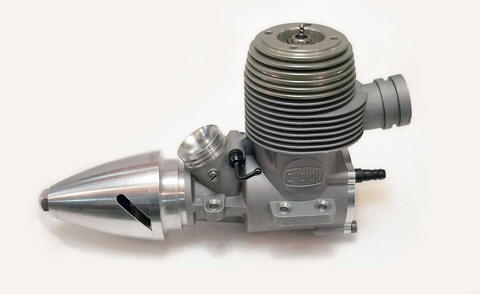
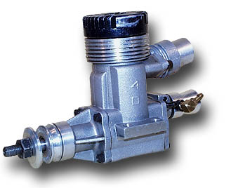
| IR .40 | |
| The IR .40, which is quite successful in Germany
and in Europe. The engine shown here, is a rear intake, rear exhaust
version. The latest, presumably even more powerful type, features a front
intake, which is pointing downwards. This makes it well suited for upside
down installation, where the intake is located on top of the fuselage, far
away from dust and dirt. The casing has four mounting lugs only, the piston is running in a sleeve with interestingly shaped transfer and exhaust ports; adjustable bearings. The manufacturer was Ravel Ibragimov. |
|
| MB .40 | |
 [click on image for other view] This photo shows an MB .40 (MB stands for Metkemeijer/Brendel). The detachable cylinder is clearly visible, as well as the enormously large transfer channels close to the exhaust. The oily fingers belong to Robbert van der Bosch. (Photo courtesy Peter van Doesburg) |
The Metkemeijer brothers have designed, built and
flown high performance .15 engines for control line team racing models for
years. At first the usage of the new .40 pylon racing engines has been
restricted to pilots from the Netherlands (like the DU airfoils), but they
have become available for mere mortals in 2001. The engines show some
technical highlights, like detachable, sleeveless integral cylinders with
extremely wide transfer ports and unique twin bearings. The latest model has
a (bench tested) power output of more than 2.5 kW at 30000 1/min and
development is still proceeding towards higher power output.
More information can be found on the Metkemeijer web pages.
|
| Jett .40 | ||
 |
Jett F3-D .40 stroke: 17.9 mm |
Former champion Dub Jett is
manufacturing a complete range of engines, including several .40 racing
engines. The high end product is the .40 F3-D engine for the FAI events, a
front intake rear exhaust engine. The catalogue also includes engines for
the Q500 and other events.
JETT Engineering, Inc. |
Last modification of this page: 21.05.18
![]()
[Back to Home Page] Suggestions? Corrections? Remarks? e-mail: Martin Hepperle.
Due to the increasing amount of SPAM mail, I have to change this e-Mail address regularly. You will always find the latest version in the footer of all my pages.
It might take some time until you receive an answer
and in some cases you may even receive no answer at all. I apologize for this, but
my spare time is limited. If you have not lost patience, you might want to send
me a copy of your e-mail after a month or so.
This is a privately owned, non-profit page of purely educational purpose.
Any statements may be incorrect and unsuitable for practical usage. I cannot take
any responsibility for actions you perform based on data, assumptions, calculations
etc. taken from this web page.
© 1996-2018 Martin Hepperle
You may use the data given in this document for your personal use. If you use this
document for a publication, you have to cite the source. A publication of a recompilation
of the given material is not allowed, if the resulting product is sold for more
than the production costs.
This document may accidentally refer to trade names and trademarks, which are owned by national or international companies, but which are unknown by me. Their rights are fully recognized and these companies are kindly asked to inform me if they do not wish their names to be used at all or to be used in a different way.
This document is part of a frame set and can be found by navigating from the entry point at the Web site http://www.MH-AeroTools.de/.
 .
.