A Race Car Wing
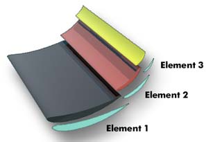
A multi-element downforce wing for a race car
This wing consists of three elements which can be adjusted individually to achieve optimum results. The main parameters are the gap between the elements and their angle of incidence.
Note: JavaFoil analyzes two dimensional sections only. This corresponds to an unswept wing of infinite span. In real world applications, wing span is limited and the flow field is affected by wing span and tip shape. Also the body of a car leads to a strong distortion of the incoming flow. Thus the results of such a two dimensional analysis represent the flow at the symmetry plane (center section) of a three dimensional wing without sweep. If large end plates are used, the flow is nearly two dimensional over most of the span.
Preparation of the Geometry
The geometry can be prepared with a CAD program which
can write the x-y-coordinates to an ASCII file. You can also use a tool
like Microsoft Excel™ to prepare the coordinates. After you have
prepared the data, you paste the complete set of coordinates including
separator lines (see below) into the the coordinate text area of the
Geometry card.
You can also generate NACA airfoil sections with JavaFoil and combine them
by copy and paste in the coordinate text area of the Geometry card.
The data format in this text area is identical to the standard x-y-tables
used for single element airfoils. The segments are separated by a
separator line.
This separator line contains dummy x- and y-values which must be larger than 999.0
| x1,1 | y1,1 |
coordinates for the first element |
| ... | ... | |
| xn,1 | yn,1 | |
| 9999.9 | 9999.9 | separator line |
| x1,2 | y1,2 | coordinates for the second element |
| ... | ... | |
| xn,2 | yn,2 | |
| 9999.9 | 9999.9 | separator line |
| x1,3 | y1,3 | coordinates for the third element |
| ... | ... | |
| xn,3 | yn,3 |
Modification of the Geometry
After you have created or imported a multi-element airfoil, you can modify its elements on the Modify card.
This card contains a list box where you can select single or multiple elements for modification. Any transformation will be applied to the selected elements only. The selection also is used to display the results of the analysis tools on the remaining cards of JavaFoil. The actual analysis is always performed for the complete airfoil - the selection affects the output only.
It is important to make sure that the outlines of the elements never intersect. If this occurs, the panel method would either find no solution at all or produce unrealistic velocity peaks, so that the boundary layer analysis will fail or deliver bogus results. Additionally the elements should not be positioned too close together as this will create similar effects (as they also occur an extremely thin trailing edges).
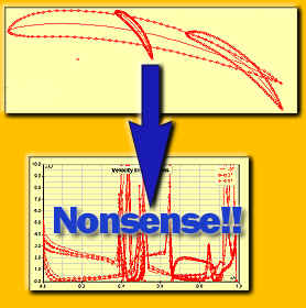
Please, don't do this...
Some Results
Note 1: All coefficients are always given for a total chord
length of 1.0. Thus a 50% scaled version of a single airfoil element (initially
having a chord length of 1.0) will create a lift coefficient of ½ the
coefficient of the full airfoil. Also the slope of the lift versus angle
of attack curve for this single element will be reduced to 50% of the full
length airfoil.
This can be confusing at first, but makes sense. The moment coefficient is
always relative to the point (x=0.25 / y=0.0). For the scaled airfoil
example above one would obtain ¼ of the initial moment coefficient (see
also note 3).
Note 2: The Reynolds number for the boundary layer analysis is based on a chord length of 1. JavaFoil adjusts this value for each element according to its actual chord length. Any roughness values or transition locations are valid for all elements. This means that a forced transition at 10% chord will force transition at 10% of the local chord of each element.
Note 3: The lift, drag and moment coefficients will be altered by the stall model (selected on the Polar card). Generally the Eppler stall model is preferred for multi-element airfoils.
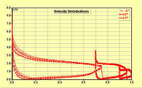
Velocity distribution on the elements.
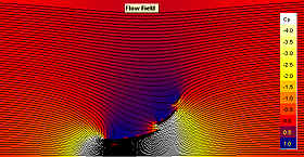
Pressure field and streamlines.