|
D |
diameter |
m |
|
N |
yawing moment |
m |
|
R |
radius |
m |
|
a |
length of suspension lines |
m |
|
e |
half distance between suspension lines |
m |
|
T |
period of one oscillation |
s |
|
m |
mass |
kg |
|
g |
gravity acceleration |
m/s² |
|
n |
speed of rotation |
1/s |
|
W |
rotation rate |
rad/s |
|
w |
pitch rate |
rad/s |
A spinning propeller produces not only thrust but also other forces and moments. Some of these effects will be discussed here.
One main effect unique to the mechanics of rotating objects are gyroscopic moments. These moments occur when a spinning object (e.g. a metal disk, a bicycle wheel or a propeller) is more or less quickly tilted.
Rotating the front wheel of y bicycle by moving the handlebars to the "right" (right hand handle back, left handle forward) creates a "rolling moment" to the left(!). Therefore when riding a bike, a turn to the right must be initiated by briefly steering to the left - the resulting gyroscopic moment makes the bike frame lean o the right and a new force equilibrium can be achieved with the handlebar close to the neutral position again.
Here we consider a typical propeller for a pylon racing model which has the following parameters
 |
, | , |
|
in standard SI units this is
|
|
, |
|
, |
|
The moment of inertia of the propeller can be estimated in different ways. The following paragraphs show the results of three different models.
The most simple model replaces each blade by a mass point located at the center of gravity of each blade. The center of gravity of the blades of a specific propeller was found by weighing a propeller cut in two pieces. The result was a center of gravity position at 30% of the radius. Then the moment of inertia can be determined as follows:
![]()
The results will be a lower bound of the true value because the outer regions of the blades are not modeled with sufficient accuracy.
The propeller can also be replaced by a solid rod of equal mass. Then the moment of inertia will be
![]()
This value will represent more like an upper limit because the blade mass is not distributed evenly along the radius - a propeller has more mass located close to the hub and less towards the tips).
Even more conservatively, the propeller can be thought of being replace by a solid thin disk of equal mass
![]()
Here it is assumed that the propeller mass is distributed evenly over the disc area.
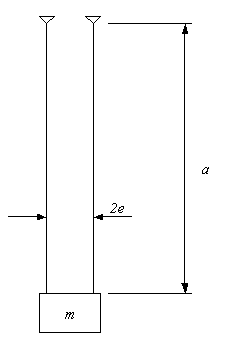
The moment of inertia can also be determined by experiment. For this the propeller is suspended from two long lines and put into oscillations. From the measured period of the oscillation T for small amplitudes w can find the moment of inertia J using the following equation
![]()
A small error will be introduced by the resistance of the air, especially if the mass of the propeller is very small.

Pendulum Experiment.
Using the pylon propeller (before it was cut into blades) the following values have been measured
|
|
, |
|
, |
|
These numbers produce the moment of inertia

While a high accuracy can be achieved with large full scale propellers, we must assume a reduced accuracy of maybe about ±20% for small lightweight model propellers.
The table shows the results of the above estimations. Except for the simple point mass model the results are fairly close. The experimental results fits between the rod and the disc model so that for practical application it seems to be justified to take the mean value of these two models.
| model | estimated moment of inertia |
|---|---|
| point mass | J = 1.056 E-5 kg m2 |
| rod | J = 7.822 E-5 kg m2 |
| disc | J = 5.867 E-5 kg m2 |
| experiment | J = 6.678 E-5 kg m2 |
Comparison of different methods to estimate the moment of inertia.
In order to simplify the following calculations, a value of J = 5.0 E-5 kg m2 has been used.
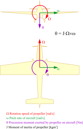
The yawing moment produced by propeller precession is
![]()
Example
| propeller RPM | ||
| moment of inertia | ||
| pitch rate | (this is a violent pitch/turn maneuver, smooth coordinated turns may exhibit about half that value) |
The resulting yawing moment is then
![]()

In case of the common propeller sense of rotation (model aircraft: clockwise when seen from the receiver) the a "pitch up" motion w ("pull") produces a yawing moment q in the direction "rudder to the right". This moment causes the aircraft to deviate towards the right. If the pitching motion w is in the "pitch down" direction ("push") the aircraft feels a tendency to turn to the left.
If for example a the model is in in knife's edge flight orientation with the left wing down and the pilot quickly deflects the elevator "up" the model yaws to the right, turning its nose skyways.
Example
| propeller RPM | ||
| power |
The resulting torque moment at the engine shaft is
![]()
This torque must be supported by the aircraft, e.g. by aileron trim. As long as the aircraft is rolling on the ground, the support is through the landing gear on the ground. Depending on track width, the wheels are loaded resp. unloaded accordingly. The different loads on the wheels produce different friction forces, and therefore a yawing moment. Assuming a track width of 200 mm the loads are uneven by +0.52 N resp. –0.52 N for the two wheels of a typical F3D model. This is a relatively small difference compared to the basic load by the model weight of about 2.5 kg (25N).
Assuming further a grass field with a friction coefficient of
![]() the yawing moment resulting from engine torque is
the yawing moment resulting from engine torque is
![]()
This moment is only about 10% of the moment caused by rapid pitch changes as they occur at the end of the takeoff run.
The wake of a propeller is swirling because of the torque of the engine. The swirling motion can be defined by the deviation of the flow direction in the wake from the flow direction outside of the wake. This swirl angle is large when the flight speed is low and becomes smaller when the flight speed is increased.
The swirling propeller wake meets the horizontal tailplanes, resulting in a rolling moment, It also interacts with the vertical fin, which is usually above the center line. This causes a side force on the fin and hence a yawing moment which must be compensated by rudder trim. Especially high powered aircraft with low RPM (high torque) produce large swirl angles at low takeoff speeds. Examples are fighters of the 1940s. Some of these aircraft therefore were equipped with vertical fins having cambered airfoil sections to avoid a constant rudder deflection for trim.
The engines of model aircraft usually run at quite high speeds which means small torque reaction moments. Therefore the swirl angle inside the wake of pylon racing aircraft is very small (less than 1 degree) and can be almost neglected.
There are even more effects to consider in some cases. An inclined propeller at angle of attack also produces a yawing moment as well as a lift force.
The yawing moment results from the fact that the blades moving up- and down see the incoming flow at different angles - the blade on the side moving downwards (the right side on a typical model aircraft) sees a larger angle of attack and is therefore producing more thrust than when the blade is moving up on the opposite side. The average thrust of the whole propeller is hence acting with an offset to the axis of rotation. When the blades are in the vertical position, this offset is vanishing. The thrust as well as the resulting yawing moment oscillates with a frequency depending on the number of blades.
The lift force can be explained by considering the flow through the propeller disk when the propeller is at angle of attack. The streamtube passing through the propeller is bent resulting in a radial force component seen as a side force or lift.
Where do you want to go now?
![]() Propulsion by Propellers
Propulsion by Propellers ![]() Design a Prop
Design a Prop ![]() Optimum Propellers
Optimum Propellers
![]() Equivalent Multiblade Propellers
Equivalent Multiblade Propellers ![]() Helicopter and VTOL aircraft Statistics
Helicopter and VTOL aircraft Statistics
Last modification of this page: 21.05.18
![]()
[Back to Home Page] Suggestions? Corrections? Remarks? e-mail: Martin Hepperle.
Due to the increasing amount of SPAM mail, I have to change this e-Mail address regularly. You will always find the latest version in the footer of all my pages.
It might take some time until you receive an answer
and in some cases you may even receive no answer at all. I apologize for this, but
my spare time is limited. If you have not lost patience, you might want to send
me a copy of your e-mail after a month or so.
This is a privately owned, non-profit page of purely educational purpose.
Any statements may be incorrect and unsuitable for practical usage. I cannot take
any responsibility for actions you perform based on data, assumptions, calculations
etc. taken from this web page.
© 1996-2018 Martin Hepperle
You may use the data given in this document for your personal use. If you use this
document for a publication, you have to cite the source. A publication of a recompilation
of the given material is not allowed, if the resulting product is sold for more
than the production costs.
This document may accidentally refer to trade names and trademarks, which are owned by national or international companies, but which are unknown by me. Their rights are fully recognized and these companies are kindly asked to inform me if they do not wish their names to be used at all or to be used in a different way.
This document is part of a frame set and can be found by navigating from the entry point at the Web site http://www.MH-AeroTools.de/.