Numerical Methods
The design of an airfoil usually starts with the definition of the desired or required characteristics. These can be a certain range of lift coefficients, Reynolds- or Mach numbers, where the airfoil should perform best, stall characteristics, moment coefficient, thickness, low drag, high lift, cavitation (for hydrofoils), insensitivity with regard to dust and dirt, easy to build (flat bottom) or any combination of such requirements. When these requirements have been written down, the next step would be to look around, what's available. If there is an airfoil available, which perfectly fits the desired conditions, why create a new one? Often there is no existing airfoil, which fulfills all requirements, or the designer believes, that he can design something new with improved performance. Starting from this point, each designer has his own way and his preferred tools to proceed. Some like to use an inverse design code (like the Eppler code) to prescribe flow parameters and get the resulting geometry (airfoil) from the code. Others like to use a starting airfoil and use analysis codes (or a wind tunnel) to continue in a trial and error style (albeit with a lot of experience) to find a better airfoil shape. This second method is often used in combination with a numerical optimization code: a computer tries hundreds or even thousands of different airfoil shape modifications until it cannot find further improvements. A drawback of the numerical trial and error optimization process is that it can take a long time, and that the optimization programs tend to move into a corner of the requirements: the resulting airfoil might indeed have a low drag and high lift, but maybe only in a very small operating range and it may have catastrophic stall characteristics. It is very difficult to tell a computer, what the desired stall characteristics should look like, or what you expect from different flap settings. Currently a good designer is still necessary to get good results, but he can use the computer and numerical optimization as a tool to perform time consuming polishing work or to get hints on possible improvements.
The selection of an airfoil for a model aircraft depends mainly on the lift
and drag characteristics of the airfoil. If no experimental data are available,
theoretical methods can be used to get an approximation of these data.
Whereas the lift can be calculated reasonable well from the frictionless
pressure- respectively velocity distribution on the airfoil surface, the
friction drag can be determined by an analysis of the boundary layer with a
lesser degree of accuracy.
There are several methods for the design and analysis of airfoils available. This section briefly presents two of the most popular computer codes suitable for low Reynolds number airfoils:
The data sheets of my airfoils show results which were calculated by these two codes. My page «analyze an airfoil» uses a proprietary code, whose boundary layer module is a rewrite of Eppler's integral boundary layer method.
Professor Richard Eppler is a pioneer in the field of computational aerodynamics. He wrote his first codes using punched paper strips, the high speed main memory at these times was a magnetic drum, which could hold several bytes! - Nah, not mega- or kilo-, just bytes.
Eppler developed a very fast and elegant design method, based on conformal mapping, which is the heart of his computer code. Because an airfoil also has to operate outside of its design point(s), a fast integral boundary layer method and (for the analysis of given airfoils) an accurate third order panel method (parabolic velocity variation) was added. Furthermore the code offers possibilities to modify the geometry, to calculate drag polars, and various plotting options. Due to its early roots, the computer code has been developed as a batch code. Textual and graphical output is directed to files, which makes the FORTRAN 77 code easily portable and system independent. On the other hand, the input files are quite cryptic and hard to handle for beginners. The elaborate description of theory and code [14] even contains an (now outdated) version of the FORTRAN-IV program.
The strength of the code is the design part and the fast analysis part, which makes it very well suited for the design task. The results of the integral boundary layer method agree astonishingly well with experiments, if the Reynolds numbers are above 500'000. The design module can be used to design very smooth airfoils shapes, including the leading edge region, which is often difficult with other codes. On the other hand, the design method is quite abstract and difficult to handle for beginners.
The boundary layer analysis is performed using the calculated, inviscid (without friction) velocity distributions as input; there is no direct coupling between boundary layer flow and the external flow field. Transition prediction is performed by testing the boundary layer parameters against a set of empirically derived transition relations, which work quite well for attached flow in a wide range of Reynolds numbers.
In the low Reynolds number regime the results are usually not very accurate if a laminar separation bubble or larger separated flow regions occur. This is a result of the integral boundary layer method, which simply cannot model separation (this would require some sort of coupling between boundary layer analysis and the calculation of the external flow). The code has a option to perform a displacement iteration in order to take the displacement effects of the boundary layer into account, but there is no direct interaction, as, for example, in Xfoil. Recent (2007) additions to the code however, are an improved model of laminar separation bubbles and turbulent separation. The code itself is available for a fee directly from Prof. Richard Eppler in Germany or from his US distributor Dan Somers.
This code also includes design as well as analysis tools, which have been combined very comfortably, with ease of use in mind. The code is intended as an interactive application, but because it does not directly make use of a proprietary window system, it is quite portable and can be used in batch mode by input redirection. The design module of the FORTRAN 77 code has to be used as a redesign method, i.e. you need a starting geometry, whose velocity distribution can be modified, and you have to be very careful to avoid waves and wiggles when adding changes to the leading edge region. It is practically impossible to design the leading edge region as smooth as with Eppler's method.
The analysis module consists of a 2nd order panel method (linear varying velocity), which cannot achieve the accuracy of Eppler's panel module. But in contrast to Eppler's simple boundary layer method Drela has implemented a more sophisticated method, which takes the boundary layer into account while solving for the flow field. Thus the interaction between boundary layer and external flow is modeled quite realistic and the code can also handle small to medium sized separated regions. When the separation is getting larger or extends into the wake, the results are getting worse, but usually are still acceptable for an impression of the airfoil behavior. The transition prediction, which is of utmost importance for low Reynolds number airfoils, is based on a so called e^n method, which is used as a simplified envelope method. In some cases, the errors introduced by this envelope method can be quite large though.
The disadvantage of the more complex model is the much longer calculation time, which compares to Eppler's analysis method by a factor of 20. Most calculations shown on this web were performed with XFOIL version 5.4, which produced more realistic results when compared with the more recent versions. Some of the later versions like 5.9 seems to give good and realistic results, though. Since December 2000, Xfoil can be downloaded from its WEB page.
Some people have the impression, that an experiment, where they can measure everything up to umpteen digits behind the decimal, are the only truth. The people who are doing the real work, i.e. performing measurements at an experimental facility, like a wind tunnel, know better. It is extremely difficult to provide well defined test conditions and to make accurate measurements, especially on airfoils at Reynolds numbers below 500'000.
Some important points are the facts, that
Unfortunately not all wind tunnel experiments are documented as well as the results from the tests at the University of Illinois Urbana-Champaign (UIUC). Usually only one drag polar per Reynolds number is given and the user has no idea about fluctuations or errors in the system. The following plots show the published data for the E 374, as it has been investigated at the UIUC. The symbols represent the data, as sampled at four different spanwise locations; the line connects the mean values for each angle of attack (this is what you will find in the final publication). I can assure you, that the bandwidth of these results at lowest Reynolds numbers is not unusually large and is not a sign of poor measurement techniques. It is a matter of the physics of the flow.
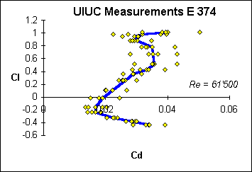 |
At this low Reynolds number of 61'500 the data points are scattered in a wide band. |
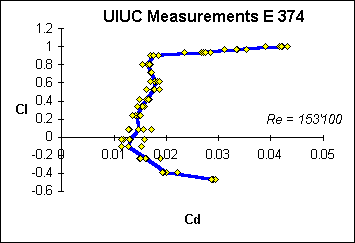 |
At medium Reynolds numbers the scatter is considerably reduced. |
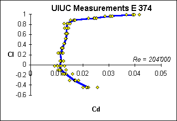 |
Increasing the Reynolds number moves the scatter to the corners of the laminar bucket. |
As you can see, the band width at Reynolds numbers above 150'000 is quite
narrow, as long as you focus around medium lift coefficients. Increasing or
decreasing the lift coefficient can lead to separation, usually starting at the
trailing edge and moving more or less slowly towards the leading edge. The flow
in separated regions is neither stationary nor two dimensional, which introduces
additional scatter into the forces and pressures.
These spanwise variations of lift and drag can occur due to wind tunnel
deficiencies, non uniform model accuracy and local separation bubbles. In most
experiments the lift coefficient is determined by a force measurement, giving a
mean value for the whole model, but the drag coefficient is measured locally.
Most modern drag measurements are performed at several spanwise locations, but
not all of them. For example the drag coefficients, published in [20],
were sampled at a single spanwise location. The reader is referred to [12],
[13] and [17]
for further discussion of the problems of tests at low Reynolds numbers, as well
as to the section «MH 32: Wind Tunnel Results».
Something, which seems to be never (?) published, is the time history of the measurements, which might yield an even wider scatter band. Drag measurements can be performed by a single sensor, moving through the wake and sampling the total and the static pressure at different locations at different times, or by using a wake rake, sampling at different locations at the same time (depending on the equipment). Thus the sampling rate and sampling time will have some influence on the results, especially when periodic fluctuations of the flow occur.
Remark:
The purpose of this section is not to blame the people who
contribute to the excellent work at UIUC or other facilities - these guys are
doing excellent and hard work, which is appreciated very much by so many all
around the world. The scatter of the experimental data is just a matter of fact,
caused by the underlying physics.
When comparing experimental and theoretical results, you should bear in mind, that neither wind tunnels nor computers perfectly represent the reality. As discussed above, wind tunnels have shortcomings like fixed walls, turbulence, noise and model quality, whereas theory is always based on a mathematical model of the real world - assuming this and neglecting that. A typical comparison is given below; at lower Reynolds numbers the discrepancies can be even larger.
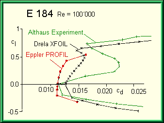
Comparison of theoretical with experimental results.
The figure above shows a typical comparison between both theoretical
analysis methods and experimental results at low Reynolds numbers. The
experiment shows the strong influence of a laminar
separation bubble, which roughly doubles the drag coefficient. The Eppler
code (voersion of 2000) cannot cope with laminar separation bubbles, but issues
a warning for all the calculated data points, saying that there might be a
separation bubble. Drela's XFOIL (version 5.4) takes the laminar separation
bubble into account, but under predicts the drag. Thus both methods cannot
predict the drag values at Reynolds numbers below 200'000 if laminar separation
occurs, but hint the user that something might be happening.
My experiences with XFOIL indicate, that it tends to shift the polars to higher
lift coefficients and that the simple panel method (in conjunction with the
spline method) has some problems with leading edges, which often results in
jaggy velocity distributions even for perfectly smooth airfoils.
It is very, very difficult to make a fair comparison of airfoils at low Reynolds numbers. On the one hand, numerical methods have serious shortcomings, but can be used to judge airfoils under comparable conditions. On the other hand, experiments are not only difficult and time consuming, but can also yield very different results even in the same wind tunnel, due to the three dimensional nature of laminar separation bubbles and spanwise variations in lift and drag. These variations can be much bigger than the differences between different airfoils, thus making a comparison of two dimensional polars, as measured by a single wake rake questionable.
Last modification of this page: 21.05.18
![]()
[Back to Home Page] Suggestions? Corrections? Remarks? e-mail: Martin Hepperle.
Due to the increasing amount of SPAM mail, I have to change this e-Mail address regularly. You will always find the latest version in the footer of all my pages.
It might take some time until you receive an answer
and in some cases you may even receive no answer at all. I apologize for this, but
my spare time is limited. If you have not lost patience, you might want to send
me a copy of your e-mail after a month or so.
This is a privately owned, non-profit page of purely educational purpose.
Any statements may be incorrect and unsuitable for practical usage. I cannot take
any responsibility for actions you perform based on data, assumptions, calculations
etc. taken from this web page.
© 1996-2018 Martin Hepperle
You may use the data given in this document for your personal use. If you use this
document for a publication, you have to cite the source. A publication of a recompilation
of the given material is not allowed, if the resulting product is sold for more
than the production costs.
This document may accidentally refer to trade names and trademarks, which are owned by national or international companies, but which are unknown by me. Their rights are fully recognized and these companies are kindly asked to inform me if they do not wish their names to be used at all or to be used in a different way.
This document is part of a frame set and can be found by navigating from the entry point at the Web site http://www.MH-AeroTools.de/.