
Basically, hydrofoils are like airfoils, just used in water. They can be used on propeller blades, as lifting surfaces or in keels and rudders. In most of these applications a high lift to drag ratio is required, which usually drives the design to higher lift coefficients.
Water can change from a liquid to a gaseous state - under certain conditions it starts to boil. While it is demonstrated in millions of kitchens each day that water starts to boil when it is heated to about 100 degrees Celsius, this process also depends on the pressure. When some water is enclosed in a container and the container is evacuated, the water will boil even at room temperature. The state change occurs, whenever the environmental pressure is dropping below the so called "vapor pressure". Heating does not change the environmental pressure, but reduces the vapor pressure of water until it drops below the environmental pressure. When water flows around an airfoil shape, the local pressure drops below the undisturbed pressure (pressure coefficient CP < 0). If this pressure drop is large enough, the vapor pressure can be reached on the surface of the airfoil and a small vapor bubble starts to develop, which can grow into a large "cave" of vapor. This process is called "cavitation". Similar to a separation bubble in air, cavitation largely increases drag and often also reduces lift. A loss of lift can even lead to disaster, e.g. provoke a spinout of a surfboard, a situation in which the lift (side force) of the fin is lost. Additionally, the collapse of larger vapor bubbles may lead to vibrations and even structural damage (remember that the density of water is 1000 times as large as the density of air). Damage due to cavitation often is a problem for marine propellers, turbines and pumps.
Therefore it is very advisable to use airfoils only in a certain angle of attack range to avoid cavitation.
Remark: a second effect may occur on hydrofoils, which are operated close to the free surface: "ventilation" occurs, when the suction region on the foil is strong enough to suck air from the free surface down to the foil's surface. The result is similar to cavitation: a rapid loss of lift. Ventilation can be avoided by means like fences or by unloading the root region of a fin which operates close to the surface.
The critical pressure coefficient CP, crit depends mainly on the vapor pressure of the water, the flow velocity and the immersion depth of the foil:
If the pressure coefficient in any region of the airfoil becomes lower than CP, crit, cavitation will occur. The graph below shows critical CP values for three speeds and three depths.
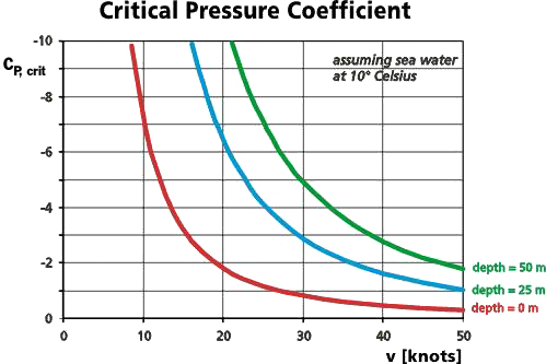
Limiting CP, crit values over flow velocity for different water depths. The curves show clearly, that the additional pressure due to depth allows for lower CP, crit values and thus higher loads at the same speed. In all cases the critical pressure coefficients drop fairly fast with increasing speed.
The analysis of the pressure distribution of an airfoil at various angles of attack yields the lift coefficient and the minimum pressure coefficient on the surface of the airfoil for each angle of attack. This minimum pressure often occurs close to the leading edge. A plot of this minimum pressure coefficient Cp* versus lift coefficient is shown below. The graph also contains horizontal lines corresponding to forward speeds of 15 and 20 knots for a depth of 0. The corresponding CP values are taken from the graph above.
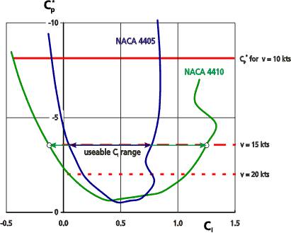
Cp* envelopes for two airfoils and comparison with the CP, crit values for different speeds.
Intersecting these airfoil specific curves with the critical pressure coefficient according to a certain flow velocity and water depth yields the useable range of lift coefficients. If the lift coefficient or angle of attack drives Cp* to lower values (more negative or upwards in the graph) than the critical pressure coefficient, the local vapor pressure will be reached and the water will begin to boil - cavitation occurs.
The 5% thin NACA 4405 shows suction peaks much earlier than the thicker NACA 4410, which results in a wider range of lift coefficients for the thicker airfoil. It can also be seen that the usable range of lift coefficients shrinks with increasing forward speed. There is a speed limit above which no cavitation free flow is possible. The only way to move that fast is to accept cavitation and switch to "super-cavitating" sections. These have different shapes, similar to airfoils for supersonic flow (e.g. wedges). Any flow with cavitation requires different numerical models, capable of handling "multi-phase" flows (water + steam); you can use JavaFoil only up to the onset of cavitation.
Cavitation free airfoils for a wide range of lift coefficients must avoid suction peaks and will usually have large regions of almost constant velocity - similar to high speed airfoils designed to keep the local Mach number just below the sonic limit M = 1.
[Considerations for Hydroprops]
Last modification of this page: 21.05.18
![]()
[Back to Home Page] Suggestions? Corrections? Remarks? e-mail: Martin Hepperle.
Due to the increasing amount of SPAM mail, I have to change this e-Mail address regularly. You will always find the latest version in the footer of all my pages.
It might take some time until you receive an answer
and in some cases you may even receive no answer at all. I apologize for this, but
my spare time is limited. If you have not lost patience, you might want to send
me a copy of your e-mail after a month or so.
This is a privately owned, non-profit page of purely educational purpose.
Any statements may be incorrect and unsuitable for practical usage. I cannot take
any responsibility for actions you perform based on data, assumptions, calculations
etc. taken from this web page.
© 1996-2018 Martin Hepperle
You may use the data given in this document for your personal use. If you use this
document for a publication, you have to cite the source. A publication of a recompilation
of the given material is not allowed, if the resulting product is sold for more
than the production costs.
This document may accidentally refer to trade names and trademarks, which are owned by national or international companies, but which are unknown by me. Their rights are fully recognized and these companies are kindly asked to inform me if they do not wish their names to be used at all or to be used in a different way.
This document is part of a frame set and can be found by navigating from the entry point at the Web site http://www.MH-AeroTools.de/.