Basic Design of Flying Wing Models
Preface
A survey of the available literature on the topic of flying wing and
tailless model airplanes shows, that in most cases, the airfoil selection
is mentioned, but no reliable data for the selection are available. Due to
the dedicated work of various modelers, a huge collection of airfoil
coordinates is available today [UIUC],
[Bender/Wiechers] - a comparable set of aerodynamic data is
more difficult to find, though. This situation and,
the numerous questions of modelers, concerning the performance and the
selection of airfoils for flying wing models, initiated this paper. On
this web page, you will find a way to perform the necessary calculations
for stable flying wing models. The accompanying collection of airfoil
coordinates and polars has been published in [29].
|
An indoor flying wing model by R. Eppler in 1942. |
Airfoils for Flying Wings
Tailless planes and flying wings can be equipped with almost any
airfoil, if sweep and twist distribution are chosen accordingly. Thus, the
one and only "flying wing airfoil" does not exist. However, if we want to
design a tailless plane with a wide operating range, the wing should have
a small amount of twist only, or none at all, to keep the induced drag at
reasonable levels throughout the whole flight envelope. Under these
conditions, the wing must not create a large variation in moment
coefficient, when the angle of attack is varied. This makes it necessary,
to use airfoils with a low moment coefficient. In the case of an unswept
wing ("plank"), even an airfoil with a positive moment coefficient is
necessary, to avoid upward deflected flaps under trimmed flight
conditions. Such airfoils usually have a reflexed camber line.
|
A modern radio controlled F3B flying wing model of 1994. |
Longitudinal Stability
Like its full sized cousins, each model airplane should have a minimum
amount of stability, i.e. it should be able to return to its trimmed flight
condition after a disturbance by a gust or a control input. How much stability
is required, depends on the pilots personal taste: contest pilots prefer a
small stability margin, beginners like to fly with a large margin. Here, only
a brief introduction into the topic will be given, which will make it possible
to find a first guess for the center of gravity and a reasonable combination
of sweep and camber for a flying wing.
1. Unswept Wings (Plank)
While the horizontal tailplane provides the necessary amount of
longitudinal stability on a conventional plane, it is the wing, which
stabilizes an unswept wing. In most cases, airfoils with reflexed
(s-shaped) mean lines are used on flying wing models to achieve a
longitudinally stable model.
Some important Aerodynamic and Mechanical Facts
To understand, why a reflexed airfoil is able to provide longitudinal
stability to a wing, two things are important:
- Total Force and Moment, c/4 point
-
The pressure forces, which act on the surface of each wing section, can
be replaced by a single total force and a single total moment. Both act at
the quarter-chord point of the airfoil. When the angle of attack
changes (e.g. due to a gust), the moment stays nearly constant, but the
total force changes. Increasing the angle of attack increases the force.
- Center of Gravity
-
Translations and rotations of "free floating" bodies are performed
relative to their center of gravity. When the angle of attack of a plane
changes, the plane rotates (pitches) around its center of gravity (c.g.).
Equilibrium
Let's have a look at a trimmed flight condition, where all forces and
moments are in equilibrium and let's compare a conventional, cambered airfoil
with an airfoil with a reflexed camber line. The moments and forces for this
trimmed state are denoted with an asterisk (*). The forces are the weight of
the model m, multiplied with the gravity acceleration g (9.81m/s)
and the aerodynamic lift L, which have to cancel out (sum of forces
in vertical direction equals zero). The drag forces are neglected here. The
sum of the moments around c.g. (caused by the airfoil moment M
and the lift force L, acting at a distance from c.g.) must
also be zero.
| conventional airfoil
with camber |
airfoil with
reflexed mean line |
| Equilibrium State |
 |
 |
| This airfoil has a nose heavy moment. As stated above, the
center of gravity is also the center of rotation of the wing. When it is
shifted behind the c/4 point, the air force L* in front of
the c.g. counteracts the nose heavy moment M* to achieve
equilibrium. The distance between c.g. and c/4 point is
depending on the amount of M*. A symmetrical airfoil has M*=0,
which means we have to place the c.g. at the c/4 point. |
The reflexed camber line makes the moment coefficient
positive, which means, that the moment around the c/4 point is
working in the tail heavy direction. Therefore the center of gravity has to
be located in front of the c/4 point to balance the moment M*
by the lift force L*. The larger the moment (-coefficient) of the
airfoil, the larger the distance between c/4 and the c.g.
for equilibrium. |
| Disturbed State |
 |
 |
| When the angle of attack is increased (e.g. by a gust), the
lift force L increases. Now L>L* and the tail heavy moment due to
the lift is larger than the moment around c/4, which still is
M=M*. Thus the wing will pitch up, increasing the angle of attack
further. This behavior is instable and a tailplane is needed to stabilize
the system. |
Here, we have the air force acting behind the c.g.,
which results in an additional nose heavy moment, when the lift increases.
With L>L*, the wing will pitch down, reducing the angle of attack,
until the equilibrium state is reached again. The system is stable. |
As we learned above, an unswept wing with a reflexed airfoil is able to
stabilize itself. Its c.g. must be located in front of the
c/4 point, which is also called neutral point (n.p.).
The distance between the neutral point (quarter chord point for an unswept
wing) and the center of gravity is defining the amount of stability - if the
c.g. is close to the n.p., the straightening moment is small
and the wing returns (too) slowly into its equilibrium condition. If the
distance c.g. - n.p. is large, the c.g. is far ahead of the
c/4 point and the wing returns quickly to the equilibrium angle. You
will require larger flap deflections to control the model, though. If the
distance is too large, the wing may become over-stabilized, overshooting its
trimmed flight attitude and oscillating more and more until the plane crashes.
A measure for stability is the distance between c.g. and n.p.,
divided by the mean chord of the wing. Typical values for this number for a
flying wing are between 0.02 and 0.05, which means a
stability coefficient sigma of 2 to 5 percent. We can
express the equilibrium of moments around c.g. for our design lift
coefficient  by
by
 ,
,
which can be transformed to find the moment coefficient needed to satisfy a
certain stability coefficient:
 .
.
| Example |
We want to use an unswept flying wing (a plank) for ridge
soaring and decide to use a target lift coefficient of
=0.5. We want to have
a stability coefficient of 5% and are looking for a matching
airfoil. We calculate the necessary moment coefficient
Cm = 0.5 * 0.05 = +0.025.
Searching through a publication about Eppler airfoils [28],
we find, that the airfoils E 186 and E 230 could be used for our model. |
2. Swept Wings
2.1 Neutral Point and Stability
We have already learned, that the center of gravity must be located in
front of the neutral point. While the n.p. of an unswept, rectangular
wing is approximately at the c/4 point, the n.p. of a swept,
tapered wing must be calculated. The following procedure can be used for a
simple, tapered and, swept wing. First, we calculate the mean aerodynamic
chord length  of a tapered wing,
which is independent from the sweep angle:
of a tapered wing,
which is independent from the sweep angle:
with the root chord lr, the tip chord
lt and the taper ratio
 .
.
We can also calculate the spanwise location of the mean chord
, using the span b,
 .
.
The n.p. of our swept wing can be found by drawing a
line, parallel to the fuselage center line, at the spanwise station y.
The chord at this station should be equal to.
The n.p. is approximately located at the c/4 point of this
chord line (see the sketch below).
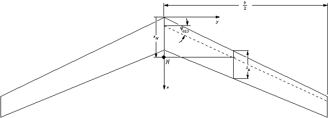
Geometric parameters of a tapered, swept wing.
Instead of using the graphical approach, the location of the neutral point
can also be calculated by using one of the following formulas, depending on
the taper ratio:
 , if taper
ratio > 0.375
, if taper
ratio > 0.375
 , if taper
ratio < 0.375.
, if taper
ratio < 0.375.
The c.g. must be placed in front of this point, and the
wing may need some twist (washout) to get a sufficiently stable wing.
2.2 Twist
The selection of the location of the c.g. to be infront of the
n.p. is not a guarantee for equilibrium - it is only a requirement
for longitudinal stability. Additionally, as explained above for unswept
wings, the sum of all aerodynamic moments around the c.g. must be
zero. Because we have selected the position of the c.g. already to
satisfy the stability criterion (c.g. in front of n.p.), we can
achieve the equilibrium of the moments only by airfoil selection and by
adjusting the twist of the wing. On conventional airplanes with a horizontal
stabilizer it is usually possible to adjust the difference between the angles
of incidence of wing and tailplane during the first flight tests. On the other
hand, flying wings have the difference built into the wing (twist), which
cannot be altered easily. Thus it is very important to get the combination of
planform, airfoils and twist right (or at least close) before the wing is
built. Again, the calculation of these parameters is quite complex and shall
not be presented here; the relations are shown in great detail in [27].
Here I will present a simple, approximate approach, which is based on two
graphs, and can be used for swept, tapered wings with a linear airfoil
variation from root to tip.
We start with the same geometric parameters, which we have used for the
calculation of the n.p. above. Additionally, we calculate the aspect
ratio (AR = b²/S, where S is the wing area) of the wing. The
selection of the airfoil sections also defines the operating range of the
model. Airfoils with a small amount of camber are not well suited for slow,
thermaling flight, but good for F3B flight style and ridge soaring. We can
design the twist distribution for one trimmed lift coefficient, where the wing
will fly without flap deflections. This lift coefficient will usually be
somewhere between the best glide and the best climb performance of the
airfoil. With the selected lift coefficient Cl of the airfoils, we
can also find the moment coefficient Cm0.25
from the airfoil polars. If we plan to use different root and tip sections, we
use the mean value of the moment coefficient of the two airfoils. The required
twist of the wing can be combined from two parts:
- Geometric Twist
- This is the twist, which is built into the wing as the difference between
the x-axis of the root and the tip section. It corresponds to the angle
difference between main wing and tailplane of conventional planes and can be
easily measured. A positive twist means a smaller angle of incidence at the
tip section (washout). Large geometric twist angles can be used to stabilize
wings with small sweep angles or highly cambered airfoils, but have the
drawback of creating large amounts of induced drag, when the wing is operated
outside of its design point. The aim of the following paragraphs is to find
the geometric twist.
-
- Aerodynamic Twist
- If we select airfoils with different zero lift angles, we can reduce the
amount of geometric twist. The difference between the zero lift directions is
called aerodynamic twist and we need airfoil polars to find the zero lift
angle. Also, a small or even positive moment coefficient reduced the required
amount of geometric twist, and improves the off design performance of the
wing.
-
Finding the Required Twist ßreq
Using graph 1, we enter the graph with the aspect ratio AR on the
horizontal axis, and draw a vertical line upwards, until we intersect the
curve, corresponding to the sweep angle of the c/4 line. Continuing
to the axis on the left border, we find the standard value
b*req for the required twist angle.
This standard value is valid for a wing, which:
-
is trimmed at
= 1.0 and,
-
has a stability coefficient of
s* =10% (see above),
and
-
uses airfoils with a moment coefficient of zero.
From the standard value we calculate the true, required twist angle, using
the formula inset into the graph. Therefore, we calculate the ratio of our
target lift coefficient to the standard lift coefficient (CL/)
and the ratio of our desired stability coefficient to the standard
 . We see, that a reduction of the lift
coefficient to CL=0.5 also
reduces the required twist by 50%. Also, if we use a smaller stability margin
s, we need a smaller amount of twist.
. We see, that a reduction of the lift
coefficient to CL=0.5 also
reduces the required twist by 50%. Also, if we use a smaller stability margin
s, we need a smaller amount of twist.
Graph 1: Finding the required twist.
Variation of zero lift angle
If we use different airfoils at root and tip, they may have different zero
lift directions, which influences the equilibrium state. The geometric twist
has to be reduced by the difference of the zero lift directions
a0 of tip and root sections:
 .
.
Using the same airfoil for both sections, we can set
ba0 to zero.
Influence of the Airfoil Moment coefficients
The moment coefficient of the airfoils contributes to the equilibrium, and
has to be taken into account for the calculation of the twist. Graph 2 can be
used to find the equivalent twist due to the contribution of Cm,
which has to be subtracted from the required twist. If we use airfoils with
positive moment coefficients, the contribution will be positive, which results
in a reduction of the amount twist, highly cambered airfoils yield negative
values bCm, which force us to
build more twist into the wing. Similar to the previous graph, we enter with
the aspect ratio, intersect with the sweep curve and read the value for
b*Cm from the lefthand axis.
Graph 2: Finding the additional twist due to the airfoils moment
coefficient.
Again, the graph has been plotted for a certain standard condition, which
is a moment coefficient of cm* = 0.05 (note:
positive value). We apply the ratio of the moment coefficients (cm/cm*)
to find the contribution bCm of
the moment coefficient to the geometric twist. This contribution has to be
subtracted from the required twist angle, too. Using the usual, cambered
airfoils with negative moment coefficients will change the sign of the ratio
cm/cm*, which results in negative
b*Cm values. This means,
that the subtraction from breq
will actually be an addition, increasing the geometric twist angle. If we have
different airfoils at root and tip, we can use the mean moment coefficient
(cm,tip + cm,root)/2 to calculate the ratio cm/cm*.
Finally, we can calculate the geometric twist angle
bgeo, which has to be built into the wing:
 .
.
| Example |
As you have noticed, the graphs contain an example, which
is used here. We consider a flying wing model with the following data:
| wing span |
b = 2.365 m |
| chord length at root |
lr = 0.260 m |
| chord length at tip |
lt = 0.170 m |
| sweep angle at c/4 line |
j0.25 = 20° |
| design lift coefficient |
CL = 0.5 |
| root section E 182 |
cm,r = +0.01 and a0,r
= -0.3° |
| tip section E 184 |
cm,t = +0.03 and a0,t
= 0.5° |
| desired stability coefficient |
sigma = 0.05 |
We calculate the wing area S:
S = (l_r + l_t)/2 * b = 0.5085 m²
and the aspect ratio
AR = b²/S = 11.0
and the mean moment coefficient
cm = (cm,r + cm,t)/2
= 0.02 .
Using graph 1, we find b*req
= 11.8°, which has to be corrected to match our design lift coefficient and
the desired stability margin:
11.8 * (0.5/1.0) * (0.05/0.1) = 2.95° .
This means that our model would need a twist angle of 2.95°
(wash out) from root to tip, if we would use a symmetrical airfoil section.
The difference of the zero lift angle of tip and root section is
 .
.
Now we read the twist contribution of the moment coefficient from graph
2, which is b*Cm = 5.8°,
which has to be corrected for our smaller mean moment coefficient:
5.8 * (0.02/0.05) = 2.32° .
Finally, we calculate the geometric twist from
2.95° - 0.8° - 2.32° = -0.17° .
The negative value means, that we could use a small amount of wash-in!
This is because we have already enough stability due to the selection of
airfoils with reflexed camber lines. Since the calculated amount is very
small, we can use the same angle of incidence for the root and tip ribs.
Since the presented method is not perfect, we can assume an accuracy to 1
degree, which is also a reasonable assumption for the average building
skills. |
Last modification of this page:
21.05.18

[Back to Home
Page] Suggestions? Corrections? Remarks? e-mail:
Martin Hepperle.
Due to the increasing amount of SPAM mail, I have
to change this e-Mail address regularly. You will always find the latest version
in the footer of all my pages.
It might take some time until you receive an answer
and in some cases you may even receive no answer at all. I apologize for this, but
my spare time is limited. If you have not lost patience, you might want to send
me a copy of your e-mail after a month or so.
This is a privately owned, non-profit page of purely educational purpose.
Any statements may be incorrect and unsuitable for practical usage. I cannot take
any responsibility for actions you perform based on data, assumptions, calculations
etc. taken from this web page.
© 1996-2018 Martin Hepperle
You may use the data given in this document for your personal use. If you use this
document for a publication, you have to cite the source. A publication of a recompilation
of the given material is not allowed, if the resulting product is sold for more
than the production costs.
This document may accidentally refer to trade names and trademarks, which are owned by national or international companies, but which are unknown by me. Their rights are fully recognized and these companies are kindly asked to inform me if they do not wish their names to be used at all or to be used in a different way.
This document
is part of a frame set and can be found by navigating from the entry point at the
Web site http://www.MH-AeroTools.de/.
Impressum
Datenschutz