| Go to new page |
This paper has been published in: G.S. Dulikravich, proceedings of the International Conference on Inverse Design Concepts in Engineering Sciences (ICIDES), pp. 445-460, Austin TX, October 17-18, 1984.
by Richard Eppler and Martin Hepperle
Institute A of Mechanics
University of Stuttgart
Germany
Two different inverse methods are applied to the design of new propellers. The first one is based on a theory of Prandtl and Betz [1], which was revived and successfully applied by Larrabee [3]. This method starts from the optimal circulation distribution for the Propeller blade and gives simple relationships between chord and angle of attack for the optimal propeller under design conditions. The off-design cases are treated by Larrabee using a simple approximate theory. This is a good approximation as long as the off-design cases are not too far from the optimum case. This Propeller theory yields for each radial station of the blade, the lift coefficients for the design case and for the different off-design cases. Once the Propeller theory has delivered the requirements for the Propeller airfoils, the second inverse theory is applied. It computes the propeller profiles from the given velocity distributions. This theory was first published in 1957 and later combined with boundary layer computation methods [4]. This method was recently extended to subsonic compressible flow, using a method of Labrujere et al. [5]. It allows in a very simple way to consider compressibility effects as long as no locally supersonic regions are present.
It turns out that the requirements near the blade tip are exclusively determined by compressibility effects, while towards the hub the velocity specifications must consider the necessary profile thickness and viscous effects.
Details and examples including the improvements which were achieved are described.
It was shown in 1919 by A. Betz [l] that the induced loss of a propeller is minimized if the propeller slipstream has a constant axial velocity and if each cross section of the slipstream rotates around the propeller axis like a rigid disk. This ideal case cannot of course be achieved behind a propeller with a finite number of blades. Also the vortex sheets shed from the trailing edges of the blades can not move like rigid bodies. This was shown by Goldstein [2].
The energy coming from the engine is translated into thrust and into the energy contained in the propeller slipstream after the propeller has passed. The slipstream is partially a movement in the longitudinal (axial) direction and partially a rotation. The propeller jet theory considers only the longitudinal jet velocity and, thereby, the optimal case of constant jet velocity. The ideal "jet efficiency" derived from these assumptions is
| (1) |
where V is the velocity by which the propeller moves and v' is the jet velocity relative to the air being at rest before the propeller passed through. (See Figure 1.)
The propeller jet theory can be supplemented by regarding the rotation of the jet. If again the ideal case of the rigid rotation is assumed, the efficiency is
| (2) |
where ω is the rotation speed of the jet and Ω, the rotation speed of the propeller. (See Figure 1.) The rotation ω is produced by the engine torque and can be expressed by
| (3) |
where R is the propeller radius. For large V, it follows that
| (4) |
where
| (5) |
is the so-called advance ratio. Because λ is normally below 0.3, the rotational energy of the jet is smaller than its transversal energy.
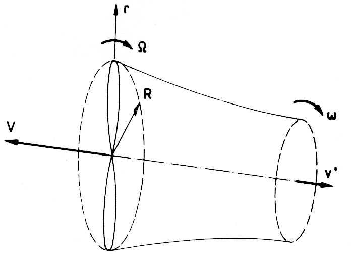
Figure 1: Sketch of the propeller and its jet. |
L. Prandtl gave a supplement to the paper of A. Betz [1], in which he derived an optimal circulation distribution Γ(r) for propellers with B blades and minimum induced loss. His result is
| (6) |
where r is the radial position on the blade,
| (7) |
and
| (8) |
| (9) |
This function F was recomputed by Goldstein [2] using better assumptions. The difference between Prandtl and Goldstein is small for high advance ratios.
A propeller design must be done for a given engine, which delivers a given amount of H horsepower at a given rotation speed ω, and for a given velocity V of the vehicle. The problem is then to get the right propeller radius R and the right jet velocity v'.
E.E. Larrabee [3] solved this problem using a simple approximate approach. His assumptions are:
From these assumptions, the induced angle of attack at each station along the blade follows. It depends, however, on v', which is still unknown. But now it is possible to compute the direction of the lift and drag forces on each blade element and to integrate the thrust T of the propeller, which is directly related to the horsepower H by
| (10) |
The efficiency η of the propeller is not yet known, but can be estimated. Because T depends on v' in a very simple way, v' can be evaluated.
Now the circulation Γ and the induced angle of attack are fixed, and the blade configuration can be determined directly, if the lift coefficient cl(r) is specified at each station r along the blade.
Also a drag coefficient cd(r) must be specified at each r. Then the efficiency η is given by Larrabee [3] by
 |
(11) |
where
![]() ,
, ![]() ,
, ![]()
Here ηi is the jet theory efficiency according to (1). Without viscous effects ε = 0 and η = ηi.
If the resulting η differs too much from the previously estimated value, an iteration must be done beginning with equation (10).
The propeller radius R can now be checked. If the estimated radius is too small, a relatively large blade chord results. If this is not acceptable, the total computation must be repeated with a larger R or a higher cl. The radius may, however, be limited by the Mach number at the propeller tip.
a) The drag to lift ratio ε in (11) contributes more to the efficiency η, when the thrust is high, which occurs in the area near the propeller tip. For normal cases, the effect of ε is small. If, however, near the tip, drag divergence due to locally supersonic areas occurs, the effect of e is considerable.
b) The neglection of the jet rotation has little effect on η, except for high advance ratios λ, which can be seen from (2). The influence on the local induced angle of attack may, however, be larger. A much more precise computational method is needed which will allow the present results to be checked.
The second author wrote a program for the described method and designed a propeller for the following case:
The diameter R = 1.6 m was selected, and the cruise condition V = 200 km/h was used for the design of the propeller. The lowest line in Figure 2 shows the lift coefficients cl(r) selected for the design procedure and Figure 3 shows the resulting chord distribution. In Figure 4, the 1ine which is lower on the right side represents the Mach numbers for the design conditions. The radius R and the lift coefficients cl(r) yield an acceptable propeller. No iteration is necessary.
It would have been possible to select higher cl values in the tip area of the propeller. But this would have required cl values which were too high for the off-design cases.
The design method of the preceding section yields a propeller for one special condition, normally the cruise condition For off-design conditions, like takeoff, a propeller analysis method must be available. This method should handle variable pitch as well.
E.E. Larrabee [3] also presented for this problem a very simple approximate method. The fundamental idea is to use an improved blade element theory.
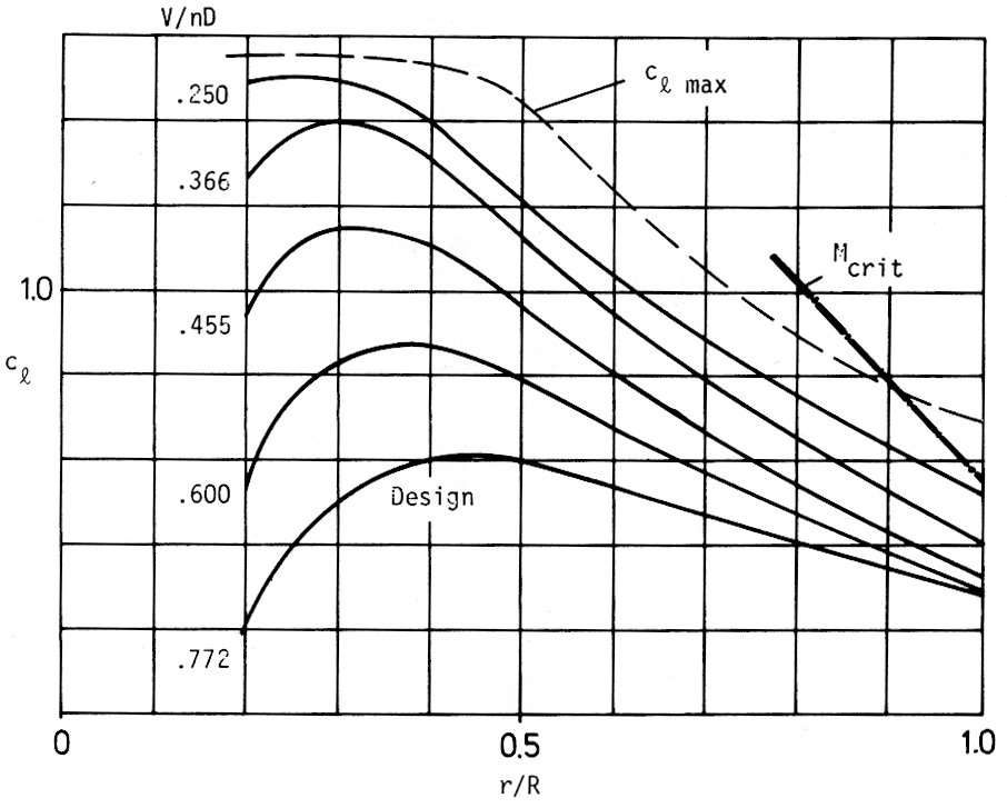
Figure 2: Lift coefficients cl on the propeller blade for various pitch angles and advance ratios. |
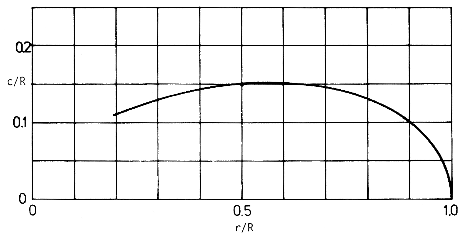
Figure 3: Resulting chord distribution of the designed propeller. |
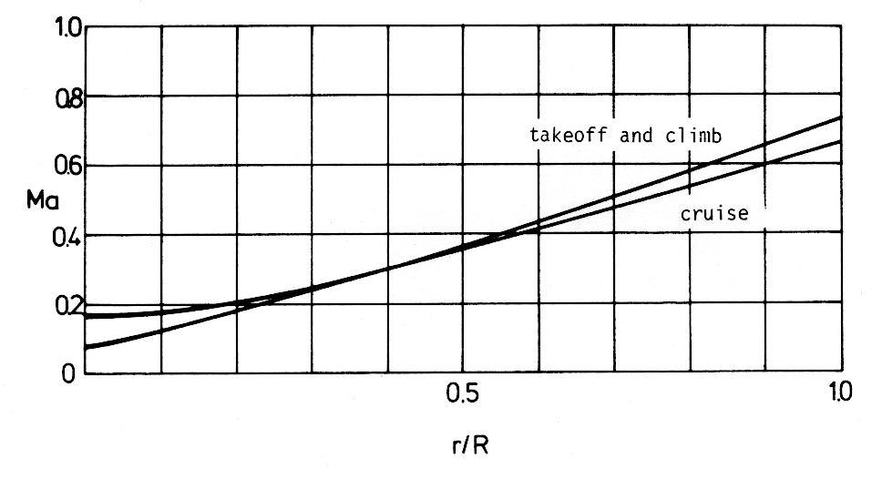
Figure 4: Mach numbers on the propeller blade for cruise and takeoff conditions. |
Without the improvement, the blade element theory yields nonzero lift at the propeller tip, because it neglects the induced velocity from other elements and their vortex systems. The improvement consists of a correction factor which correlates the induced velocity at the blade element and the average induced velocity on a ring of the propeller disk. The correction factor is taken from the optimal propeller, whose design was described in the preceding section. Thus, if such a propeller is re-analyzed using the new analysis method, the results are the same as in the design procedure. For the off-design cases, the method also yields good results with vanishing circulation at the blade tip. If, however, the off-design cases are far from the design case, larger errors must be expected. For example, the effect of a large twist deviation from the optimal propeller is underestimated. More precise methods should be used to test the results of the approximate method. The cl distributions for higher rpm and lower V for the off-design cases of the propeller discussed in section 1 are included in Figure 2. The thrust and, hence, cl increases if V decreases. Also the Mach numbers increase for the outer part of the blade due to the higher rpm (See Figure 4.)
The design case for the Propeller and the analysis of the off-design cases yield the requirements for the airfoils of the blade. There are two different critical areas.
During takeoff and climb, the Mach number near the tip is 0.74 and a cl up to 0.55 is necessary. It is obvious that the conventional airfoils used for Propeller tips, which are very thin and have flat lower surfaces, are unable to produce the required lift without strong shocks. Very high drag coefficients would therefore result. In this area, the blade sections must be designed to prevent drag divergence by increasing the critical Mach number.
The other critical limit is the maximum lift coefficient of the blade section in the area near the Propeller hub. In this area, the Mach number is much lower and not critical anymore.
To satisfy the requirements for the airfoils, the velocity distributions must have pre-specified properties. The optimal solution for airfoils near the critical Mach number is a constant velocity just below the sonic velocity. To achieve high lift coefficients, the velocity distribution must be such that the boundary layer does not separate within the operational range of lift coefficients.
There are many methods for solving the inverse problem of airfoil design. A simple method and the corresponding computer code have been presented in [4]. The code includes a method for computing friction drag and boundary layer separation as well as a Potential flow analysis program based on a higher order panel method. From there it was not a large step to include a good approximate compressibility correction. The correction of Labruiere et al. [5] was recently included in the potential flow analysis part of the computer code. It is, therefore, possible to get the compressibility effect for any airfoil whose velocity distribution was specified in the incompressible case. This effect changes the absolute value of the velocity considerably but, if the incompressible flow has constant velocity over a certain segment of the airfoil for a certain lift coefficient, the compressible flow also has over the same segment approximately constant velocity for a slightly different lift coefficient. It is, hence, easily possible to design airfoils for the compressible flow with segments of constant velocity. This is the most important airfoil design task, particularly if the critical Mach number is to be increased.
Also the solution of the multi-point design problem, which can easily be handled with the computer code [4] is transferred to the compressible solution. Only the fact that the lift curve slope is much higher near the critical Mach number must be considered.
Figure 5 shows the tip profile, 850, which must be sub-critical for cl = 0.55 and M = 0.74. It turns out that these requirements can just be satisfied by having a long segment of constant velocity just below the sonic velocity.
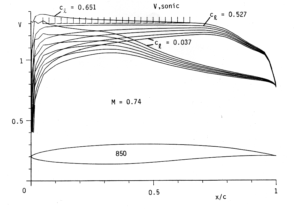
Figure 5: Profile 850 for the propeller tip r/R = 1 with velocity distributions for M = 0.74. |
The lower surface becomes critical for lower cl. For cl = +0.037, supersonic velocities are already indicated. But the cruise condition with cl = 0.28 and M = 0.69 are within the sub-critical region.
Figure 6 shows the drag polar as well as cl(α), cm(α) and boundary layer transition and separation on both surfaces. A rough surface is specified by selecting roughness factor r = 4. The very steep line cl(α) is due to compressibility effects.
The dashed line gives a rough estimate of the drag divergence for conventional, thin tip airfoil with flat lower surface.
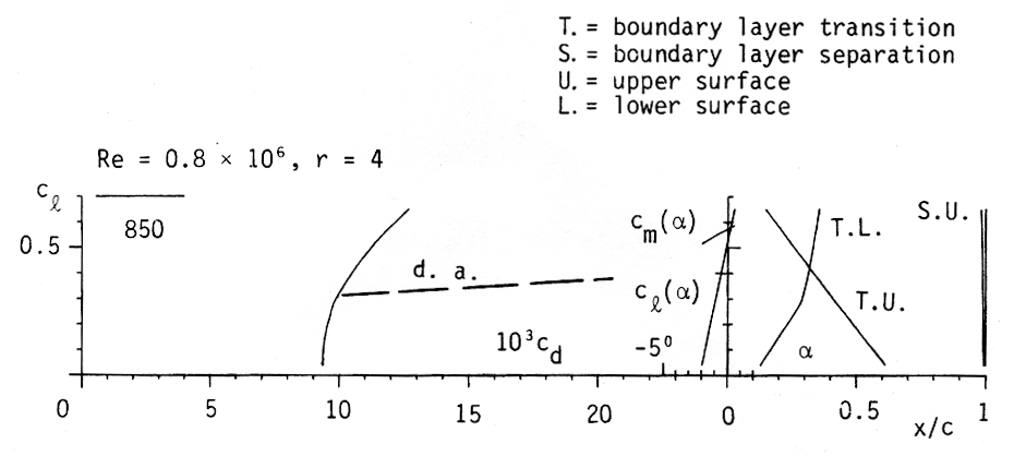
Figure 6: Drag polar of Profile 850 for M = 0.74. |
Figure 7 shows the profile, 851, developed for station r/R = 0.9. For this station, cl = 0.64 is required during takeoff, but the Mach number is lower, M = 0.67. Obviously the distance from the critical Mach number has increased, although the area of constant velocity is shorter.
Figure 8 shows the drag polar analogue to Figure 6. The dashed line again is a rough estimate for the drag divergence of an airfoil with a flat lower surface and a little more thickness than the one assumed in Figure 6.
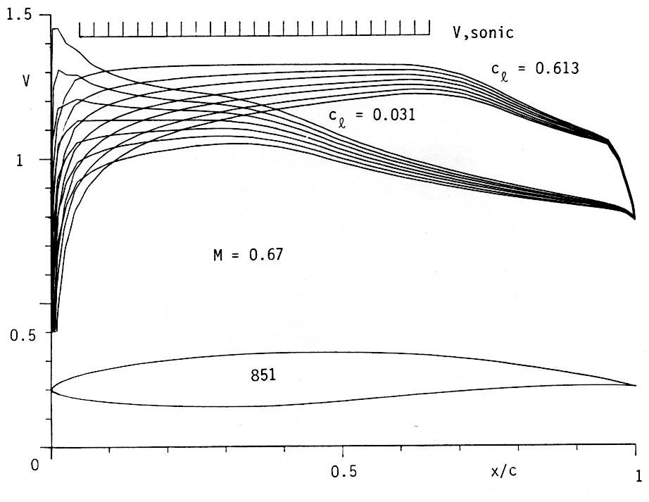
Figure 7: Profile 851 for r/R = 0.9 with velocity distributions for M = 0.67. |
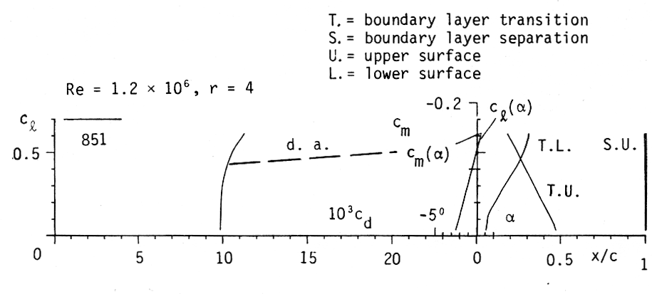
Figure 8: Drag polar of Profile 854 for M = 0.67. |
It is no difficulty to modify the design conditions for the stations closer to the hub. The length of the segment of constant velocity can decrease and the adverse pressure gradient can also decrease. The airfoils can be thicker without approaching the sonic velocity. It is possible to consider more and more the maximum lift requirements which are more critical for these stations.
A further example shows the airfoil, 854, for station r/R = 0.6. It has 13.32 % thickness and a maximum cl around 1.2, which can be seen in Figures 9 and 10.
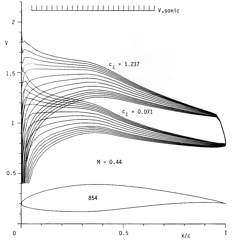
Figure 9: Profile 854 for r/R = 0.6 with velocity distributions for M = 0.44. |
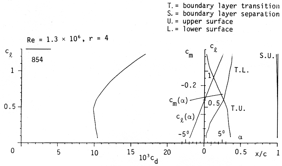
Figure 10: Drag polar of Profile 854 for M = 0.44. |
In Figure 2, the limits of the critical Mach number and cl max are shown. If the high lift conditions are always considered as soon as the sonic limit is not too close, it is possible to tailor the airfoils such that the maximum lift limit is critical only for the stations very near the hub, where the contribution to thrust and efficiency is small.
Figure 11 shows the efficiency curve for this propeller. The solid line is based on the drag data of the profiles which have been tailored for this propeller. The result is somewhat optimistic because the rotational energy of the jet is neglected. The efficiency hi from the propeller jet theory is included in Figure 11. In the area of the cruise conditions, the losses due to viscous effects are much higher than those due to the energy left in the jet. In this area, the airfoil tailoring surely pays out. It must be emphasized that an increase in efficiency of only 0.01 is very significant. It saves more than 1 % of the gasoline during the life time of the power plant, which is considerable.
Even more serious is the effect of drag divergence due to supersonic regions near the tip. (The assumed drag values are shown in Figures 5 and 7). The efficiency decreases considerably for lower advance ratios while, for cruise conditions, the lift coefficient at the tip is lower and the drag does not increase.
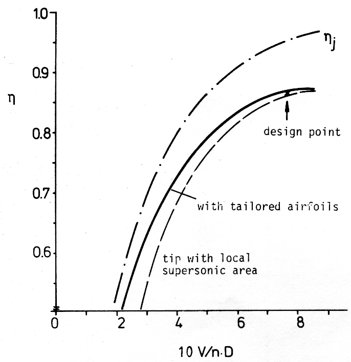
Figure 11: Propeller efficiency against advance ratio. |
Although conventional Propeller have good efficiencies, further, significant improvements are possible. If local supersonic regions are present near the Propeller tip, dramatic improvements are possible, particularly for takeoff and climb, where maximum rpm is used.
Modern engines are more efficient at high rpm and gears for rpm reduction are expensive and sensitive to vibrations and consume energy too. This is a special incentive for developing propellers for relatively high tip Mach numbers. They must be very precise and better propeller codes might be necessary for their development.
[1] Prandtl, L. and Betz, A., "Schraubenpropeller mit geringstem Energieverlust", Göttinger Nachrichten, 1919.
[2] Goldstein, S., "On the Vortex Theory of Screw Propellers", Proc. of the Royal Society (A) 123, 440, 1929.
[3] Larrabee, E.E., "Practical Design of Minimum Induced Loss Propellers", SAE Preprint 790585, 1979.
[4] Eppler, R. and Somers, D.M., "A Computer Program for the Design and Analysis of Low-Speed Airfoils", NASA TM 80210, 1980.
[5] Labrujere, T.E., Loeve, W. and Sloff, J.W., "An Approximative Method for the Determination of the Pressure Distribution on Wings in the Lower Critical Speed Range", in Transonic Aerodynamics, AGARD CP-35, 1968.