This document is a transcript of a presentation, given at the «International
Nurflügelmeeting des MFC Osnabrück» in May 1993. It was presented to a
very mixed audience of modellers and is limited to the basic effects, and not a
complete scientific treatment of the topic.
 Prologue
 The
Object of Interest
  Too
much Stress?
 Bumpy
Roads
  Induced
Drag
  And
the Big Guys?
  Epilogue
Most modern high performance flying wing aircraft with nearly elliptical lift
distributions have vertical wing tip extensions, called winglets. Flying wings
which use the bell shaped Horten lift distribution usually have no need for
vertical fins.
Winglets are also used on some conventional aircraft, as they can reduce the
induced drag similar to an extension of the wing span. Compared with the span
extension, winglets usually produce lower additional bending moments in the wing
spar, which makes them useful for retrofitting existing wings without increasing
the mass of the basic wing.
In 1992, the DLR Sailplane Symposium at Stuttgart saw a presentation from Mr.
Waibel of the well known Schleicher sailplane factory. He presented interesting
results from simple experiments, using a Volkswagen Golf (aka Rabbit), equipped
with a winglet. This paper shows the results of numerical studies which were
conducted to apply his findings to the winglets of tailless models. It is not
the aim of this paper to seek information about the optimum winglet shape and
its effect on induced drag, but to understand what happens in the region where
the winglet joins the wing and why the reduction in induced drag can be spoiled
by additional friction drag in this region. Thus we will concentrate on the
boundary layer effects.
The cover page of the 1992 «Competitors Achmer News» I found a
detailed technical drawing of three tailless planes with winglets (it could also
have been an explosion-sketch, as we call it in Germany, of the prototype flying
wing «Delaminator») as shown in the title graphics above. The three
tailless planes show interesting corners between the wing and the winglets, even
an asymmetric layout, which might be optimized for left turns on the northern
hemisphere. This drawing, which was very sketchy due to competition reasons,
forced me into a more thorough investigation of this region of flying wing
models.

For the investigation, a simple flying wing model, equipped with the MH 60
airfoil was defined and a three dimensional panel model of the configuration was
created (each airfoil section was represented by 60 chordwise panels, spanwise
clustering was used to refine the tip and root regions, resulting in about 600
to 800 panels per half wing, depending on the configuration examined). Only the
region close to the wing tip was modified, which resulted in four different
configurations:
- a rounded wing tip without winglet,
- a winglet with a large, rounded corner,
- a winglet with a sharp corner, and
- a winglet with a sharp corner, but moved downstream 50% of the tip chord.
The maximum thickness of the winglet section is approximately located at the
trailing edge of the wing tip.
All winglets had the same airfoil as the wing. The following images show the
tip region of these four configurations.


The boundary layer is very sensitive with respect to the pressure rise, which
occurs behind the point of maximum thickness of the airfoil. If the pressure
rises too quickly (which corresponds to a steep velocity gradient), the boundary
layer will transition early at best or even worse separate from the surface.
Flow separation causes large additional drag.
Comparing the flow field around a single airfoil and the airfoil winglet
combination, a fundamental difference becomes obvious: whereas the free airfoil
feels a pressure rise in one dimension only, an additional spanwise pressure
rise is imposed on the flow in the corner between winglet, as depicted below.
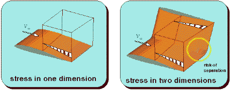
The external flow or pressure field is imposed on the boundary layer flow,
which must overcome both pressure rise components in the winglet corner. The
result is a high risk of boundary layer separation, if the winglet consists of a
simple, bent up wing tip. To remedy this unfortunate situation, the winglet can
be attached with an arc segment of large radius, to avoid the rectangular
corner. A second way to decouple the pressure rise regions of wing and winglet
is to shift the winglet downstream. By doing so, we move the front part of the
winglet into the region of the pressure rise of the wing and the winglets
pressure rise region is moved behind the wings trailing edge. Thus the winglets
region of a favorable pressure gradient (the a region, where the flow
accelerates) partially cancels out the wings pressure rise, resulting in a more
favorable situation then without the winglet.
The figure below shows the velocity distributions of the wing sections close
to the wing tip as well as isobar patterns on the wing itself. The same four
configurations are shown.
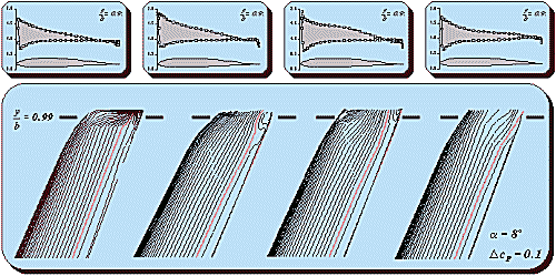
A first impression of the flow field is given by the isobar plots in the
lower part of the picture. First it can be seen, that the influence of the wing
tip shape is limited to a fairly small region of the wing, maybe 10% of the
span. A second observation is the fact, that all winglets hinder the spanwise
flow and thus the pressure drop at the wing tip, which is seen in the first
configuration, the free wing tip.
The change of the flow pattern close to the tip is also visible in the
velocity distributions in a section at 99% of the span, which is shown in an
enlarged view below.
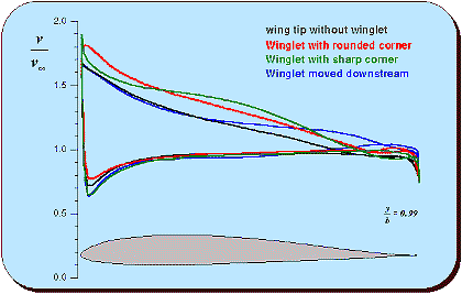
Velocity distributions close to the wingtip of the different
configurations.
The graph above shows the local velocity on the surface of the wing, at the
99% span station. The upper set of lines represents the velocity on the upper
surface, the curves falling more closely together are for the lower surface,
which is of no interest here. Starting with the black line for the wing tip
without winglets, we see that all winglet configurations raise the velocity on
the upper surface, but at different places.
- The winglet with the smooth, large fairing (red line) shifts the velocity
distribution to higher velocities, without a large distortion. Close to the
trailing edge, the velocity must reach the value of the lower side,
resulting in a steeper gradient there. This configuration is not increasing
the stress on the boundary layer very much, but it has a relatively large
surface and is more work to build.
- The winglet with the sharp corner (green) shows a quite distorted velocity
distribution, with a suction peak close to the leading edge, which can lead
to premature transition into turbulent flow. The following region up to 60%
of the chord shows a flat pressure gradient, which favors laminar flow, bit
it is followed by a steeper velocity drop towards the trailing edge, which
increases the risk of flow separation.
- Moving this winglet downstream (blue) shows almost no change in the first
50% of the chord and the velocity distribution up to 80% of the chord is
much flatter than the original airfoil. This can lead to a larger area of
laminar flow. The pressure rise towards the tailing edge is not much steeper
than that of the base airfoil, because the trailing edge velocity is also
raised. The result will be similar to the well rounded fairing
configuration, probably even better.
All the investigations above concentrated on the boundary layer and the
associated friction drag. Of course the main idea behind winglets on
conventional airplanes is to reduce the induced drag, and all the discussion
about pressure distributions and boundary layer effects would be incomplete and
questionable, if the different configurations would show very different induced
drag figures. On the other hand, the main reason for the usage of winglets on
tailless airplanes is not the possible reduction of the induced drag, but the
search for the most effective arrangement of vertical fins to achieve
directional stability - the influence on drag is an additional benefit for
tailless planes.
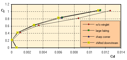
Lift coefficient versus (induced) drag, as calculated by the
panel method.
The induced drag polar above shows, that all three winglet configurations
show almost identical results in term of induced drag. There seems to be a small
advantage for the last configuration, but this is close to the limits of the
numerical method. All configurations outperform the free wing tip model - as
expected, the drag reduction is getting larger with increasing lift coefficient.
The graph does not include the friction drag, which reduces the benefit of the
winglets due to the additional surface. Taking friction into account, favors the
classical wingtip at low lift coefficients, but the total drag of the winglet
configurations will still be lower at higher lift coefficients. For the flying
wing, the winglets make a vertical fin obsolete, whose friction drag would have
to be added to the drag of the conventional wing tip configuration.
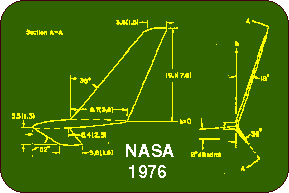
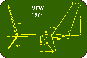
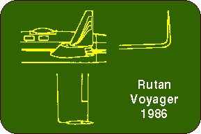
If we look at full scale aircraft with large winglets, we see, that most of
them have shifted the winglet downstream, either by reducing the chord length at
the root of the winglet (VFW, NASA) or by moving the complete winglet downstream
(Voyager). If possible, they add a curved fairing between wing and winglet. The
sweep of the NASA and VFW winglets is necessary due to the higher flight Mach
numbers, for a model airplane no sweep is needed (only to please your eyes).
Also, the dihedral of the winglet is of minor importance as is the small forward
winglet-let pointing downward.
We still have not reached the state of the art with our primitive efforts...
Last modification of this page:
21.05.18

[Back to Home
Page] Suggestions? Corrections? Remarks? e-mail:
Martin Hepperle.
Due to the increasing amount of SPAM mail, I have
to change this e-Mail address regularly. You will always find the latest version
in the footer of all my pages.
It might take some time until you receive an answer
and in some cases you may even receive no answer at all. I apologize for this, but
my spare time is limited. If you have not lost patience, you might want to send
me a copy of your e-mail after a month or so.
This is a privately owned, non-profit page of purely educational purpose.
Any statements may be incorrect and unsuitable for practical usage. I cannot take
any responsibility for actions you perform based on data, assumptions, calculations
etc. taken from this web page.
© 1996-2018 Martin Hepperle
You may use the data given in this document for your personal use. If you use this
document for a publication, you have to cite the source. A publication of a recompilation
of the given material is not allowed, if the resulting product is sold for more
than the production costs.
This document may accidentally refer to trade names and trademarks, which are owned by national or international companies, but which are unknown by me. Their rights are fully recognized and these companies are kindly asked to inform me if they do not wish their names to be used at all or to be used in a different way.
This document
is part of a frame set and can be found by navigating from the entry point at the
Web site http://www.MH-AeroTools.de/.
Impressum
Datenschutz


