Aerodynamics of
Spar&Rib Structures

"What about my
Ribs, Doc?"
Aerodynamics of
|
"What about my Ribs, Doc?" |
|
For some model aircraft, as well as full size aircraft, fabric covered rib and spar construction techniques are used. Usually they are easy and cheap to build, and offer a lightweight structure. From an aerodynamic point of view, they have the drawback of interpolating from the desired airfoil shape to something we don't know, between the ribs.
Note: As some readers of these pages have pointed out, the fabric between the ribs of full scale airplanes is sucked upwards by the low pressure field on the upper wing surface. The covering on the lower surface may be pressed upwards. There is not much data available of these effects (I found only one report with some tiny bit of information about such bulging - NACA TN-428).Experiments with typical model aircraft wings showed only negligible deformations, which is caused by the smaller spacing between the ribs and, mainly, by the lower flight speed of model airplanes. The local pressure on the surface is proportional to the square of the velocity. This means, that the surface pressures on a sailplane model, flying at 10 m/s, are only 10²/40² = 1/16 of the forces on a sailplane cruising at 40 m/s.
Wind tunnel tests at low Reynolds numbers have shown quite good results in terms of drag for plastic film covered rib structures [18, 30], but there seems to be no systematic investigation of the effects occurring on covered rib structures.
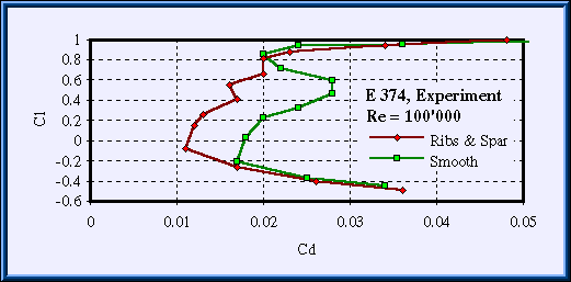
Fig. 1: Polars of the E 374 for a typical, high quality wind tunnel model and a
structure built up from ribs and spars, covered with plastic film. Data was taken from [18].
Some numerical results will be presented here to shed a light on the aerodynamics of covered rib structures.
Remark:
While you might be used to terms like spanwise lift distribution, I will talk now about spanwise sag
distributions and sag factors. If you know a better word to describe this, please let me know. Terms like
these are usually not taught in German schools.
A typical built up structure consists of longitudinal ribs, which are attached to a leading edge box and to a trailing edge box. The leading edge box usually also houses the main wing spar. While the boxes are covered with wood, the surface of the wing between them covered with a flexible material, which only supported by the ribs. In reality, the shape of the surface between neighboring ribs, and the leading and trailing edge boxes is also controlled by the mechanical properties of the cover material. The real surface geometry could be calculated by using a finite element membrane model, but it will be very difficult to find the correct tension forces acting on the membrane. They depend on the amount of dope used to paint the surface, or the amount of heat applied to shrink a plastic film cover and on the aerodynamic forces acting on it.
To simulate the effect of a the cover material sagging between the ribs, a simple model was used for the present investigation (see figure 2). On the two dimensional airfoil two points were marked: one point at x/c=25%, representing the end of the leading edge 3D box, and one point at 85% chord, corresponding to the beginning of the trailing edge box. Then, a straight line, connecting these two points, was said to represent 100% sag (sag factor). This would be the shape of the cover material, if there were no ribs between the leading and the trailing edge boxes.
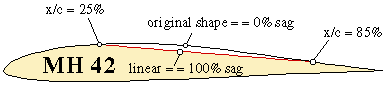
Fig. 2: Wing section, showing various degrees of the cover material sagging between
ribs.
Due to the ribs, which add a spanwise component to the stress in the membrane, the true shape will be somewhere in between the 100% and the 0% shape. For the following results, it was assumed, the a maximum of 60% sag occurs between two ribs. The spanwise distribution of the sag factor was represented by a quadratic curve.
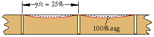
Fig. 3: Rear view of the wing, illustrating the spanwise sag distribution as well as the
rib spacing.
Initially it was planned, to perform only a strip wise, two dimensional airfoil analysis for various spanwise sections, so that any effects caused by spanwise flow components could not be modeled. It was uncertain, whether some crossflow would occur due to observed spanwise differences in the pressure distributions. This lead to the numerical analysis of a more realistic, three dimensional wing segment, whose results are presented first. To illustrate the three dimensional shape of the pressure distribution, a rather large angle of attack of 10° has been chosen. For the two dimensional analysis a more realistic angle of 3° was used.
To check the three dimensional pressure distribution and the possibility of spanwise crossflow, a wing segment, made of 5 ribs, spaced in spanwise direction by 25% of the chord length, was analyzed (figure 4). To determine the flow field, a grid was created to solve the Euler equations. Boundary layer effects were neglected.
 |
The wing surface was modeled by 60 cells around the airfoil and 40 cells in spanwise direction. The distance to the far field was spanned with 64 cells. At both ends the wing segment was placed between parallel walls and a mirror boundary condition was applied there. |
| Fig. 4: The wing segment of 4 covered panels, as used for the three dimensional analysis. |
| The results for a 10° angle of attack case (figure 5) show the pressure landscape created by the ribs and the cover material between them. It can be seen, that the influence of the walls is limited to the outer panels of the wing segment. The pressure distribution corresponds quite well to the results of the two dimensional analysis. The kink between the rigid and the flexible parts creates suction peaks, which can be seen between at the connection to the D-nose and at the junction with the trailing edge. Behind the leading edge suction peak a region with a steep, concave pressure rise can be seen, which causes the separation bubble to move forward to the beginning of this region. | 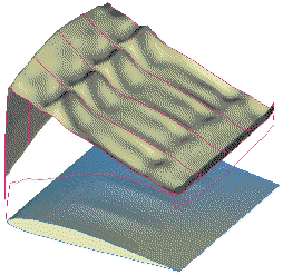 |
| Due to the more concave pressure distribution, the pressure on the covered area is
slightly higher than along the ribs. The suction peak at the trailing edge junction is quite small and introduces only a slightly increased pressure rise towards the trailing edge. This small peak seems to have only a small influence on the characteristics of the wing. |
Fig. 5: Distribution of pressure coefficient cp on the upper surface of the wing segment at 10° angle of attack. Suction peaks are visible near the leading edge and at the end of the D-nose, between the ribs. |
Fluid particles moving along a rib, close to the end of the D-nose, see low pressure regions to the right
and to the left. These introduce a small tendency into the flow, to move towards the center of a panel. But a
short distance behind the suction peak, the pressure on the panel center is higher than on the rib, which
drives the flow back to the rib. The crossflow velocity component is very small, in fact the maximum values
are less than 0.25% of the inflow velocity. Thus it can be assumed, that the spanwise variation in the
pressure distribution, has no effect on the behavior of the attached flow.
It is uncertain although, what happens inside a separation bubble, where the chordwise flow velocity may have
very small values too. Here, the spanwise pressure differences might have a stronger influence, and cause a
spanwise recirculation inside the bubble structure. This would be an interesting topic to examine with an
experiment. Also the question arises, whether the ribs can force the spanwise variations in drag, as shown in
[17], into a more regular, predictable pattern.
Based on the results of the three dimensional analysis, it can be assumed, that the most important effects can also be predicted by a strip wise 2D approach. Thus the boundary layer behavior was investigated using the two dimensional airfoil analysis module of XFOIL.
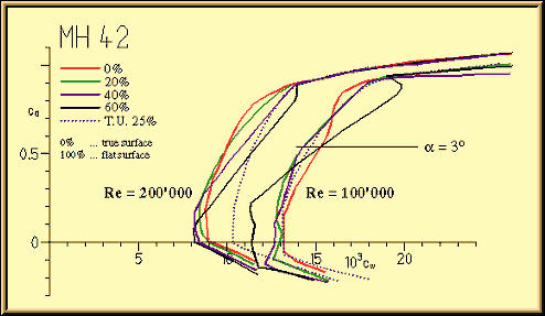
Fig. 6: Lift vs. drag polars for the MH 42, with different sag factors applied, at two
Reynolds numbers. The dotted line corresponds to a turbulator at 25% chord, placed on the upper
surface of the original (0% sag) MH 42 airfoil.
For the case of a medium lift coefficient of 0.55 at a Reynolds number of 100'000 the junction between D-nose and the covered area does not introduce enough disturbances to act as an efficient turbulator. The main effects of the sag between the ribs seem to be a forward shift and a thinning of the laminar separation bubble, which has a relatively small impact on the drag coefficient. Experimental results in [30] also show a drag reduction between the ribs, but the effect is much stronger there, despite the smaller sagging between the ribs.
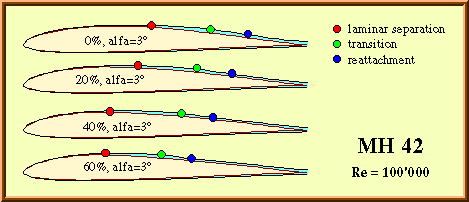
Fig. 7: Location of separation and transition for the MH 42, with different
sag factors. The lift coefficient is approximately 0.55.
Combining the two dimensional results into a three dimensional view shows the complex separation bubble more clearly (figure 8).
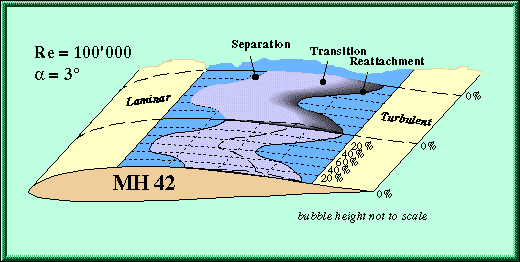
Fig. 8: Sketch of the bubble structure developing on a covered rib structure at low
Reynolds numbers.
Despite the fact, that the laminar separation bubble moves by nearly 20% of the chord length, the variation of the drag coefficient between two ribs is relatively small. The drag of the true shape (0% sag) is decreasing, when we move away from the rib. This is because the bubble moves forward and gets thinner due to the slight disturbances introduced at the end of the D-box. When we approach the center between two ribs, the bubble moves still further forward, but the drag increases. This is caused by the substantially longer length of turbulent flow, which adds more to the drag than the reduction of the bubble height. Also the pressure distribution shows a more concave pressure raise due to the flatter surface, which may contribute to the bubble height.
At higher lift coefficients, the polar for the large sag factor of 60% shows a drag increase, which is the result of a larger, further forward shifted, separation bubble due to the steeper pressure gradient. All the other polars show similar drag values as the one with a turbulator at 25% chord.
Case 2: Re=100'000, angle of attack=-2° (Cl=0.05)
When the angle of attack is reduced, the separation bubble moves to the rear part of the airfoil (figure 9). Increasing the sag factor seems to have a beneficial effect on laminar separation, which does even vanish for sag factors above 20%. For the 40% case, the thick, laminar boundary layer is close to separation, when it arrives at the trailing edge.
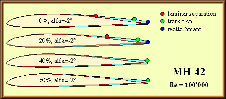
Fig. 9: Location of separation and transition for the MH 42, with different sag factors.
The lift coefficient is close to zero.
The overall drag is reduced for all sag factors, most noticeable for the 60% case. Here the concave pressure distribution seems to be responsible for the rather thin, laminar boundary layer, which extends to the trailing edge. This is also supported by the fact, that the drag is considerably lower that the fully turbulent case (turbulator at 25% chord).
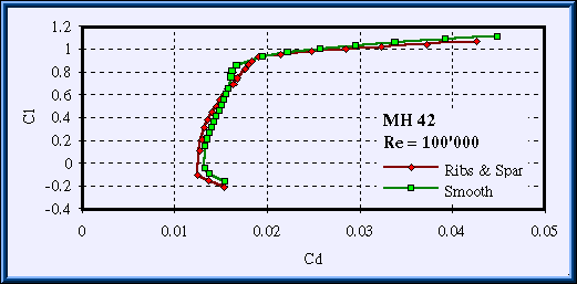
Fig. 10: Polars of the MH 42 for the true shape (0% sag) and for the covered rib structure, integrated
along the span (compare with figure 1).
At higher Reynolds numbers, the original airfoil (0% sag) shows only a very small laminar separation bubble. The dependencies between drag and sag are more straightforward than in the Re=100'000 case. At medium and higher lift coefficients, an increase of the sag factor creates a steeper, more concave pressure distribution on the covered panel, which also increases the height of the separation bubble and thus its drag. However, when compared against the turbulent case (T.U. = 25%, 0% sag), the drag of all airfoils is lower, except for a small region at higher lift coefficients, where the 60% sag airfoil develops some additional drag.
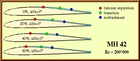
Fig. 11: Location of separation and transition for the MH 42, with different sag factors. The
lift coefficient is approximately 0.55.
It is difficult to draw general conclusions from these results. It looks like the sagging of the cover
material between the ribs seems to have a beneficial effect at Reynolds numbers of 100'000 and below. At
higher Reynolds numbers the drag increases over a wide range of lift coefficients; I would not take it for
granted, that the drag decrease, which is visible on the MH 42 at low lift coefficients, can be observed on
other airfoils. The variation on drag coefficient along the span, as calculated by two dimensional, strip wise
analysis, is relatively small.
On the one hand, it is questionable, whether such an analysis is justified and whether the results are close
to reality, on the other hand the regular structured surface my reduce the spanwise drag and lift variations,
which occur on strictly cylindrical wings. Hopefully future investigations will shed a light on these
questions. Future experimental investigations should also include local measurements of sound levels and
frequencies as well as inflow variations and details about the model quality in spanwise direction.
Last modification of this page: 21.05.18
![]()
[Back to Home Page] Suggestions? Corrections? Remarks? e-mail: Martin Hepperle.
Due to the increasing amount of SPAM mail, I have to change this e-Mail address regularly. You will always find the latest version in the footer of all my pages.
It might take some time until you receive an answer
and in some cases you may even receive no answer at all. I apologize for this, but
my spare time is limited. If you have not lost patience, you might want to send
me a copy of your e-mail after a month or so.
This is a privately owned, non-profit page of purely educational purpose.
Any statements may be incorrect and unsuitable for practical usage. I cannot take
any responsibility for actions you perform based on data, assumptions, calculations
etc. taken from this web page.
© 1996-2018 Martin Hepperle
You may use the data given in this document for your personal use. If you use this
document for a publication, you have to cite the source. A publication of a recompilation
of the given material is not allowed, if the resulting product is sold for more
than the production costs.
This document may accidentally refer to trade names and trademarks, which are owned by national or international companies, but which are unknown by me. Their rights are fully recognized and these companies are kindly asked to inform me if they do not wish their names to be used at all or to be used in a different way.
This document is part of a frame set and can be found by navigating from the entry point at the Web site http://www.MH-AeroTools.de/.