Drag of Aileron and Flap Linkages of a Sailplane Model
(Results are presented with permission of Dr. Würz)

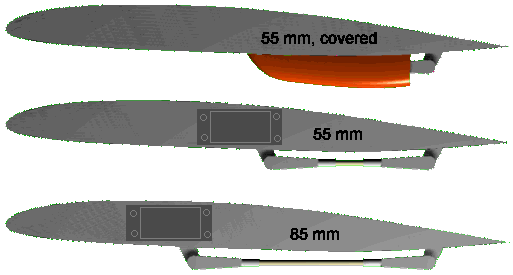
This artists impression shows all three pushrod setups
on the lower side of the wing at the same time.
Drag of Aileron and Flap Linkages of a Sailplane Model(Results are presented with permission of Dr. Würz) |
 This artists impression shows all three pushrod setups on the lower side of the wing at the same time. |
This paper is a based on work by Werner Würz, published in the papers of the ISF-Seminar¹ in December 1989 in Baden, Switzerland. Dr. Würz built and performed drag measurements on linkages, as they are used on the wings of F3B models. These models are usually equipped with flaps and ailerons, which are driven by 2 micro-servos in each wing, resulting in a total of four control horns and pushrods. Although these parts have only a small frontal area, they cause additional drag, which had not yet been examined on model aircraft.
The test setup consisted of the pushrod assemblies, mounted on a wing segment, which had been manufactured in the moulds of the F3B model «Wizard». This model is smaller than a current F3B model, but the wing section MH 42 can be considered as a representative section for these models. The tests were conducted in the "Modellwindkanal" of the Institute for Aero- and Gas Dynamics (formerly under the head of Prof. F.X. Wortmann), which is an excellent low Reynolds number wind tunnel. The combination of the wing chord of 0.2 m and the wind tunnel operating range leads to Reynolds numbers of 100'000 and 200'000 for these tests. Thus no high speed tests (speed task) were possible, but the results will be very similar at higher Reynolds numbers.
| Side view of the three linkages on the lower surface of the wing. The wing chord was 200 mm and the size of the flap was 23% of the wing chord. Standard 2 mm diameter push rods of different lenghts were used. |  |
The linkages were tested on the upper wing surface as well as on the lower surface. The drag measurements were performed by traversing a wake rake in spanwise direction behind the trailing edge of the model. The resulting spanwise drag distribution was the integrated and after subtracting the basic airfoil drag, the additional drag of the setup was calculated. The lift coefficient for each Reynolds number was chosen to represent a wing loading of 40 kg/m² (Table 1).
| Reynolds number | Lift Coefficient Cl |
|---|---|
| 100'000 | 0.75 |
| 200'000 | 0.30 |
Table 1: Reynolds number and corresponding lift coefficient.
| The plots below show four typical drag distributions, as they have been
plotted from the wake surveys. First, it can be seen, that the drag is
never constant along the span, even outside of the influence of the
pushrod or fairing. Similar results have been found later by M. Selig [31].
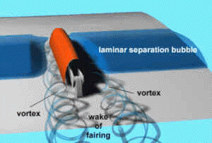
At the borders of the area of influence, a clearly visible reduction of the local drag occurs for all cases where the linkages are mounted on the upper surface. This is the result of vortices, which develop at the sides of the front linkage horn or in the corners of the fairing, respectively. These vortices destroy the laminar separation bubble on the upper surface, leading to a reduction in local drag. When the linkage is mounted on the lower surface, no such effect is visible. |

This schematic image shows how the laminar separation bubble is destroyed on both sides of the fairing. The drag in this region is reduced, whereas it increases behind the fairing due to the turbulent wake of the fairing itself. |
|
|
|
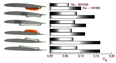
In order to make a comparison possible, the drag of each setup was normalized with an area of 0.01 m². The resulting drag coefficients are shown in the figure below.

Drag coefficients of the different pushrod types (for a reference area of 0.01 m²).
It can be seen, that the covered pushrods have the
lowest drag, and that in most cases it is better to place the linkage on the
lower surface of the wing. Only in one case, for the short, open linkage at a
Reynolds number of 200'000, the location on the upper wing surface showed lower
drag. This was due to the fact, that the base airfoil has a laminar separation
bubble at this low Reynolds number, which is partially destroyed by the servo
lever, thus reducing the local drag coefficient.
There is a remarkable benefit from covering the pushrod, even if a simple
fairing with an open rear end is used.
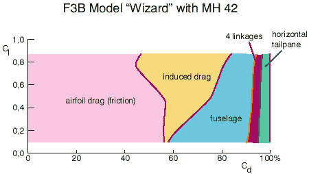
If we add the drag of four pushrods to a typical F3B plane, we find, that their contribution to the total drag is approximately the same as that of the horizontal tail plane. It might be worth, to consider internal pushrods and levers again, despite their mechanical difficulties and the risk of flutter, if the stiffness is not sufficient.

The drag components of an F3B model show the contribution of
the individual parts.
________________
¹ During the 1980s, the ISF-Seminars ("Internationales
RC-Segelflug Forum") have been an
excellent platform for the exchange of theoretical and experimental results for
application in F3B models. Building techniques as well as aerodynamic aspects
have been presented there as well as specific topics for the competition pilots,
like winches and tactics.
Last modification of this page: 21.05.18
![]()
[Back to Home Page] Suggestions? Corrections? Remarks? e-mail: Martin Hepperle.
Due to the increasing amount of SPAM mail, I have to change this e-Mail address regularly. You will always find the latest version in the footer of all my pages.
It might take some time until you receive an answer
and in some cases you may even receive no answer at all. I apologize for this, but
my spare time is limited. If you have not lost patience, you might want to send
me a copy of your e-mail after a month or so.
This is a privately owned, non-profit page of purely educational purpose.
Any statements may be incorrect and unsuitable for practical usage. I cannot take
any responsibility for actions you perform based on data, assumptions, calculations
etc. taken from this web page.
© 1996-2018 Martin Hepperle
You may use the data given in this document for your personal use. If you use this
document for a publication, you have to cite the source. A publication of a recompilation
of the given material is not allowed, if the resulting product is sold for more
than the production costs.
This document may accidentally refer to trade names and trademarks, which are owned by national or international companies, but which are unknown by me. Their rights are fully recognized and these companies are kindly asked to inform me if they do not wish their names to be used at all or to be used in a different way.
This document is part of a frame set and can be found by navigating from the entry point at the Web site http://www.MH-AeroTools.de/.